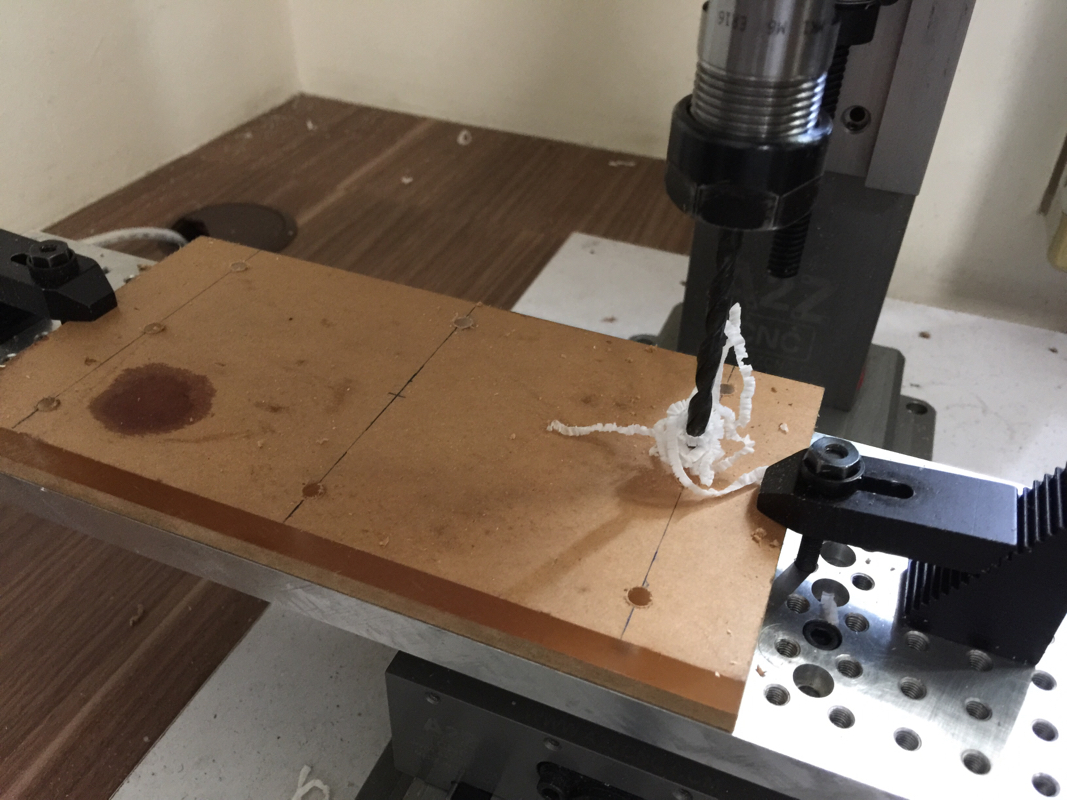
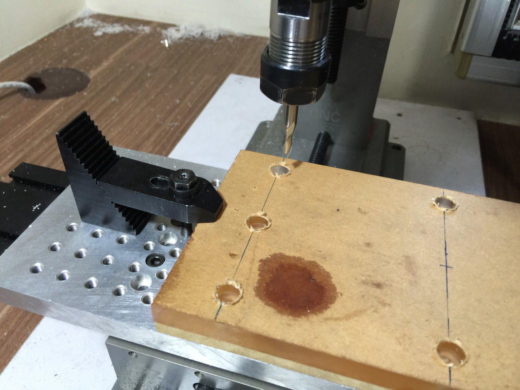
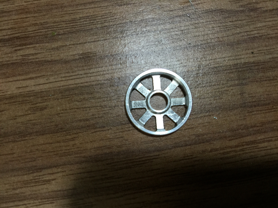
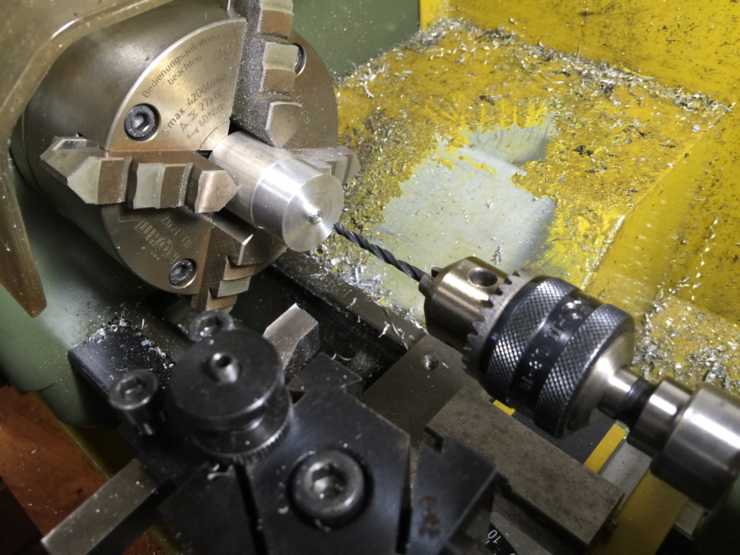
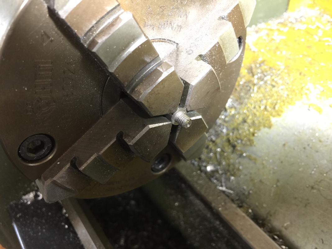
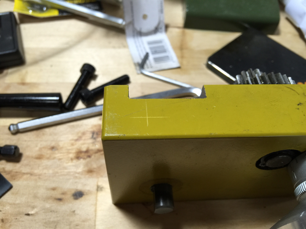
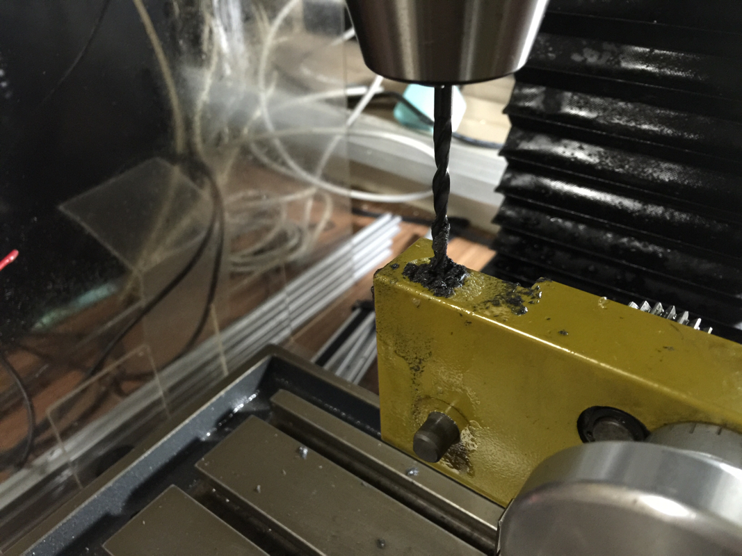
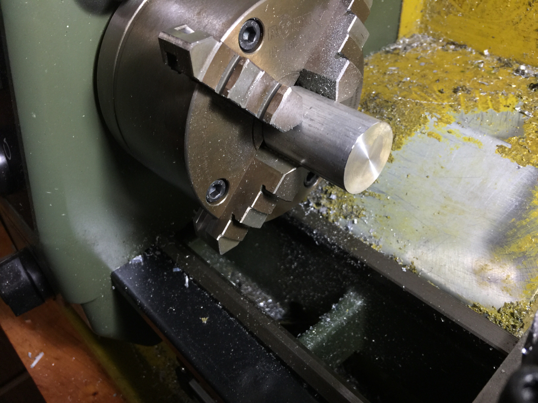
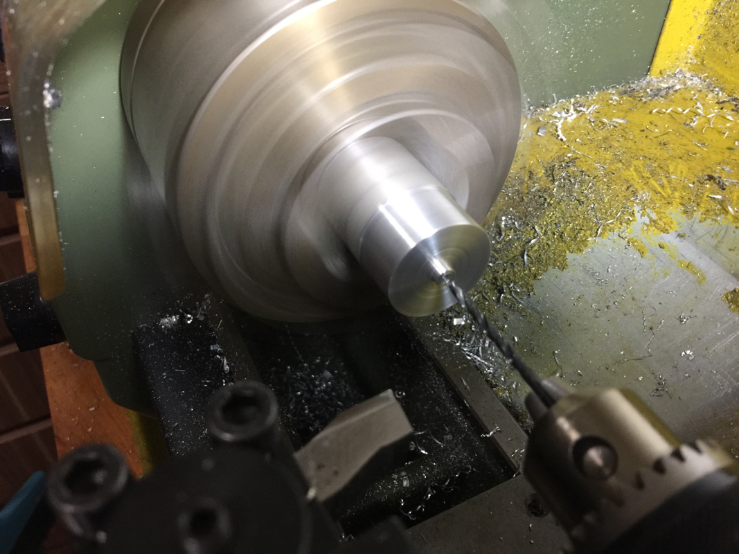
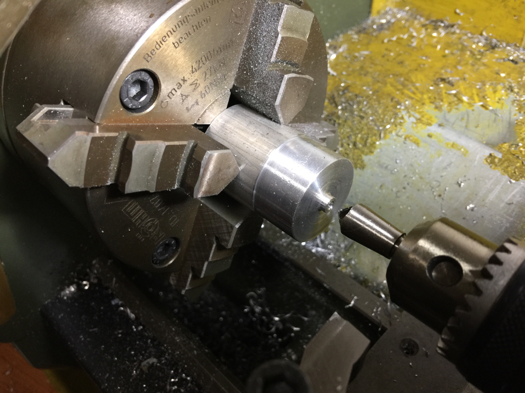
After the failure in removing the roller from the fixture, I wrote to the Thai gentleman again seeking his advice. While waiting for his reply, I decided to drill through each recess with a smaller diameter size drill. This way, I can tap the rollers out after they've been machined. It will be tedious doing it this way as I'll have to re-indicate the fixture for every batch.
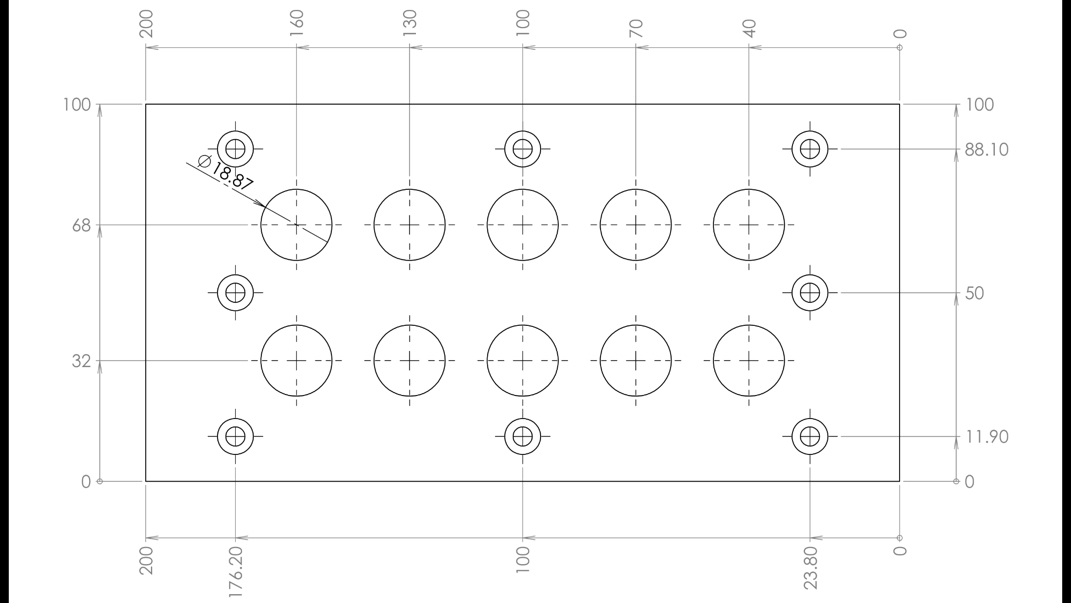
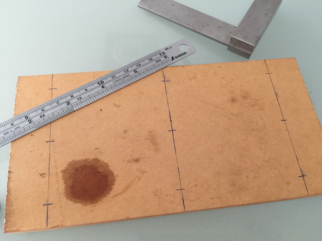
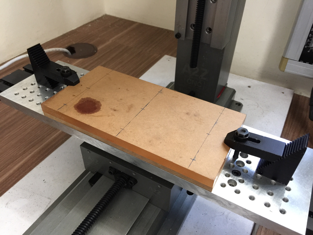
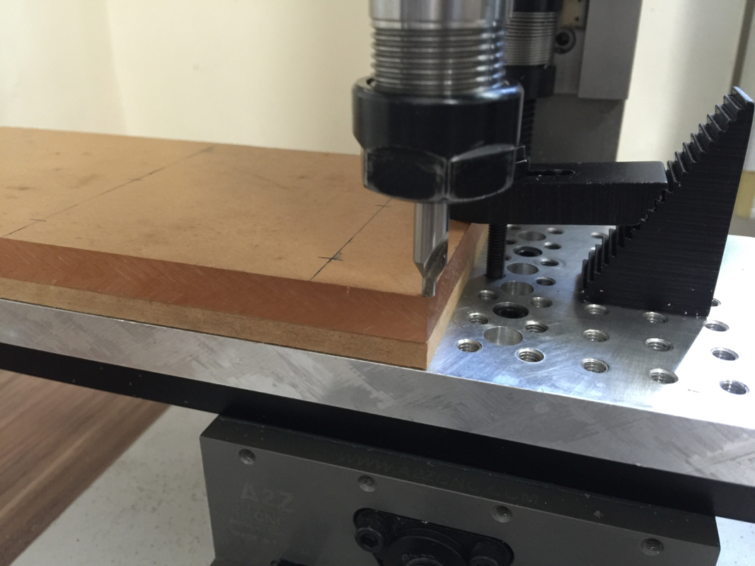
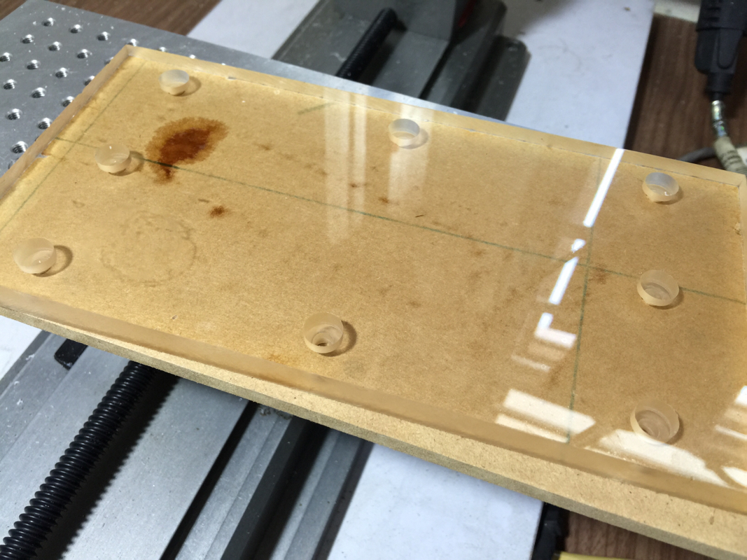
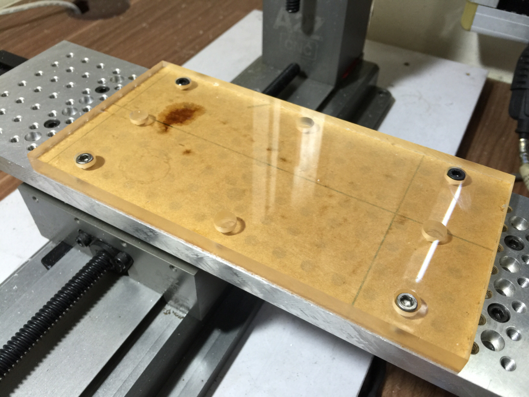
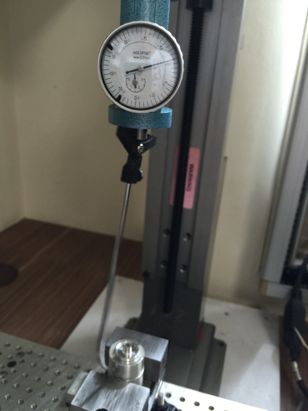
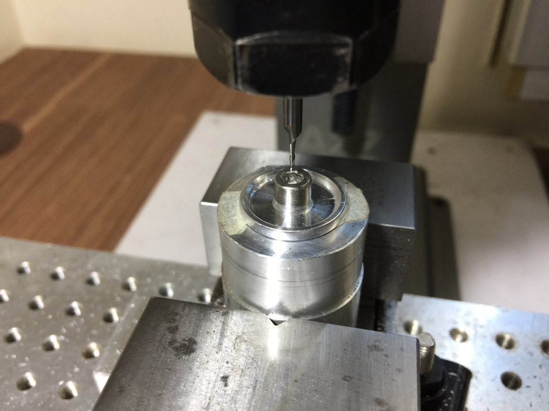
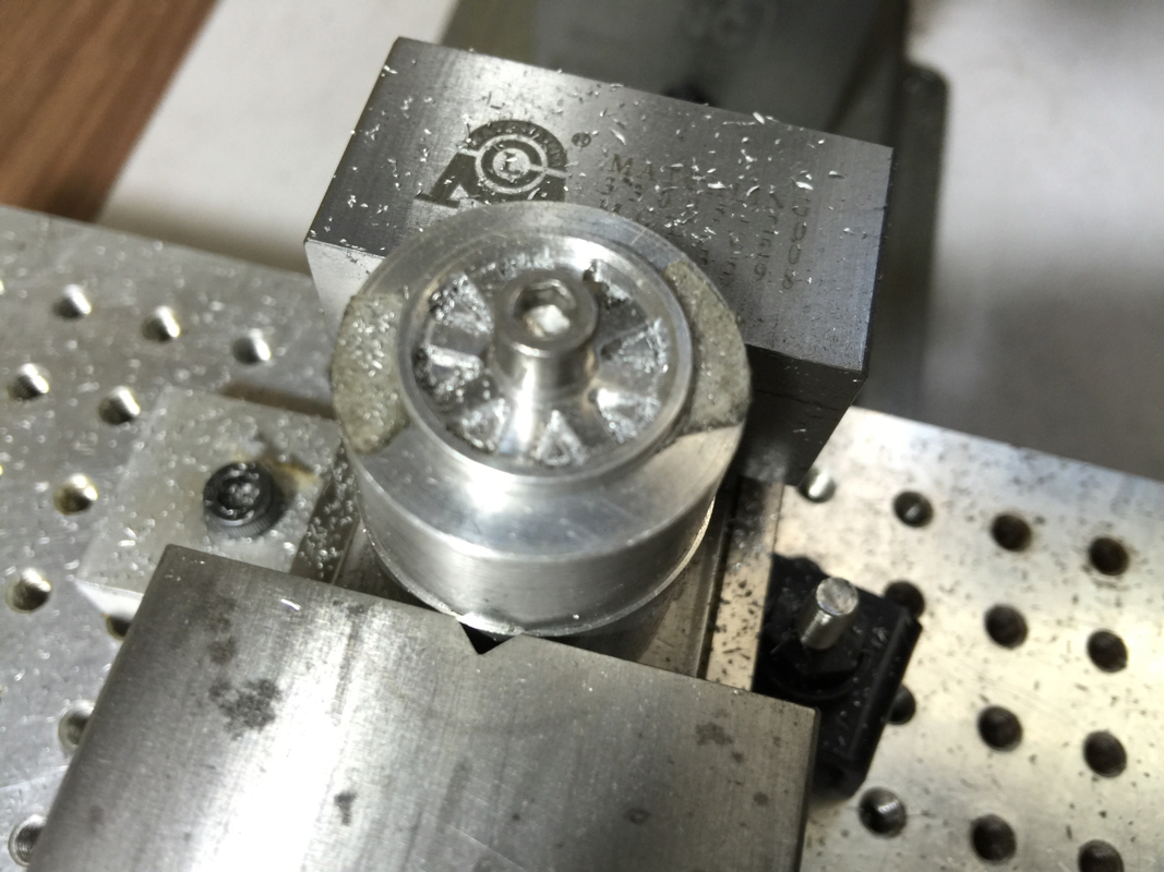
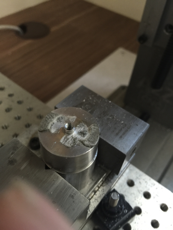
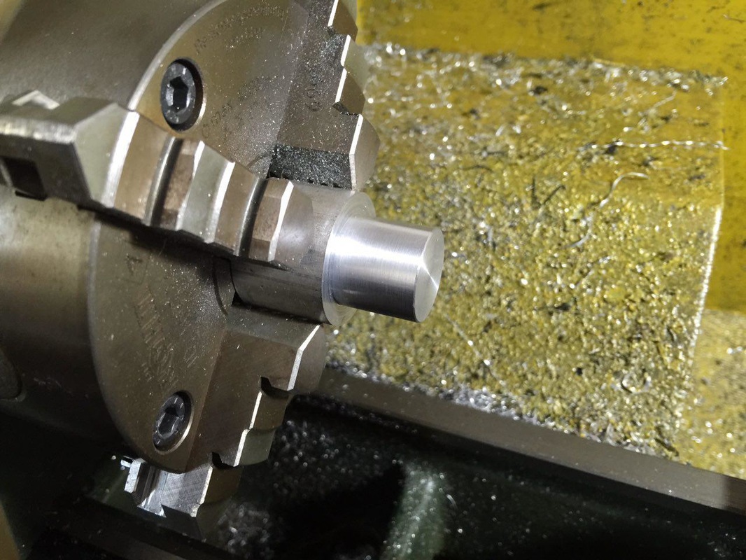
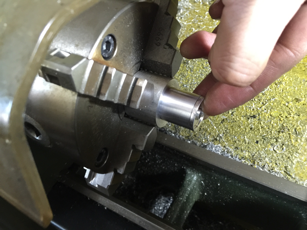
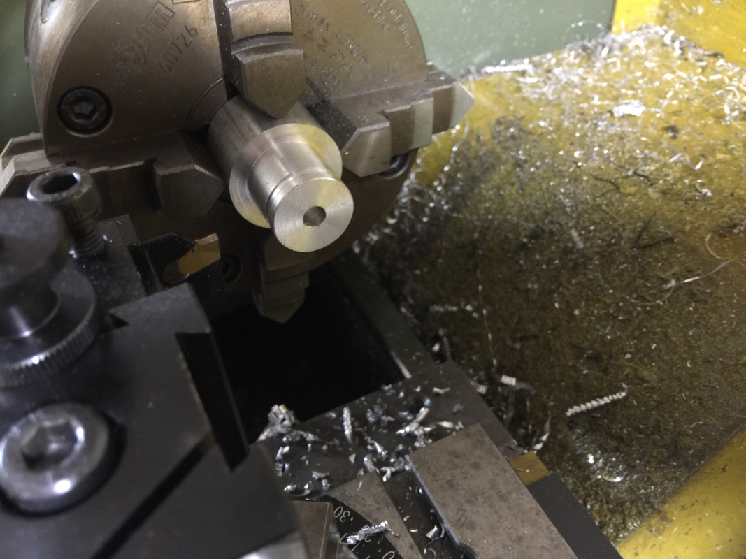
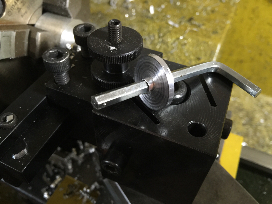
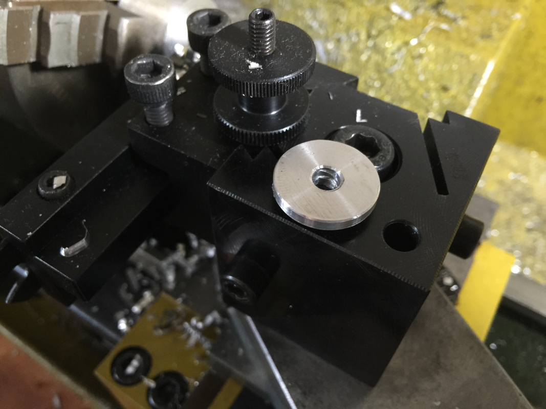
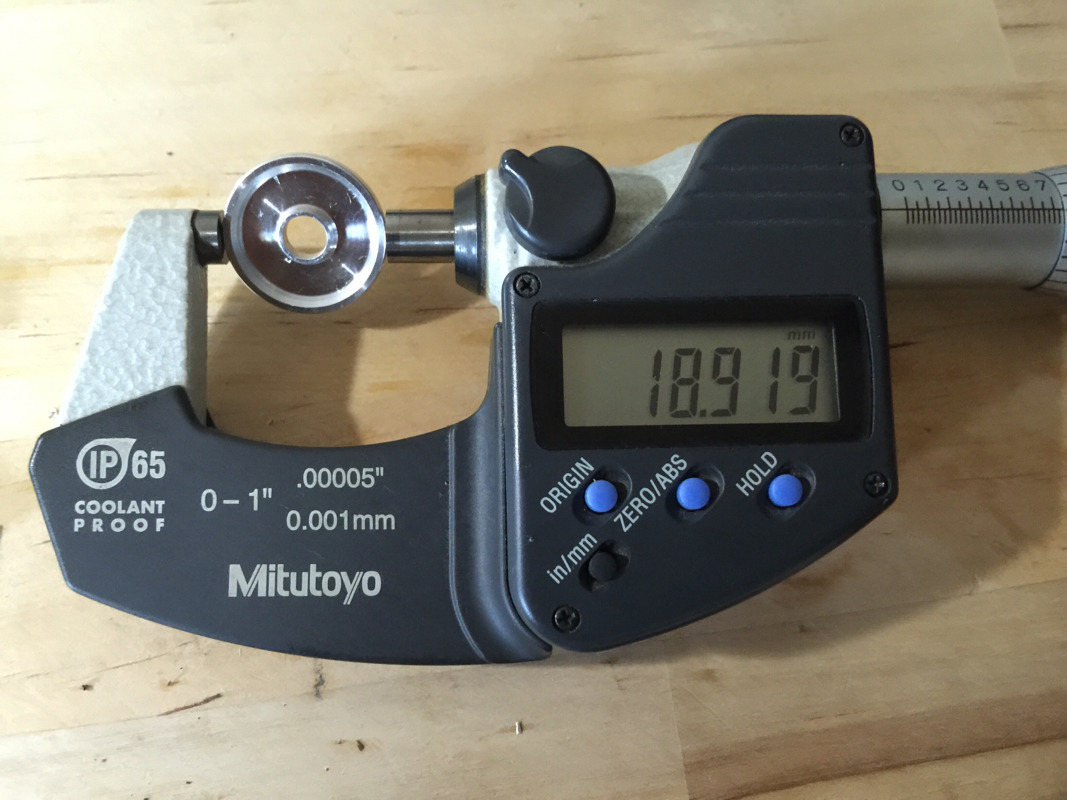
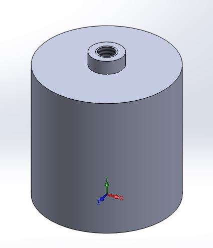
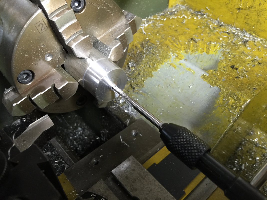
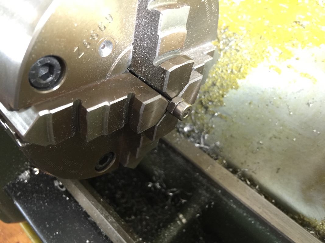
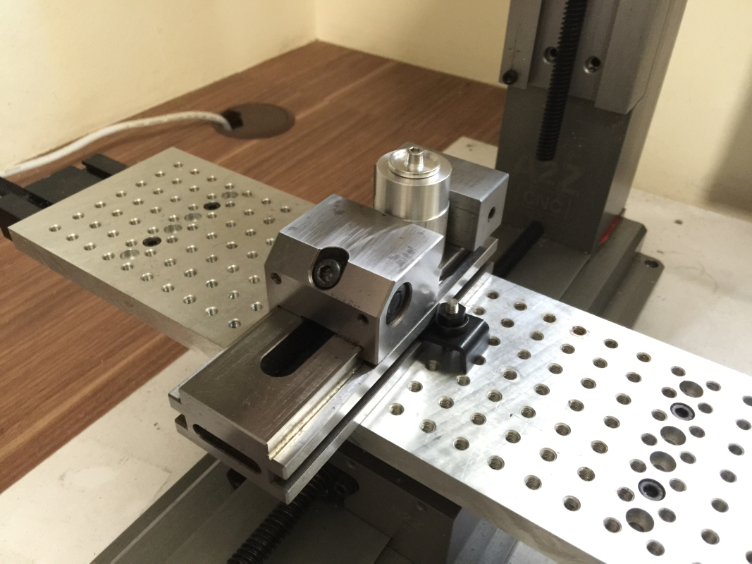
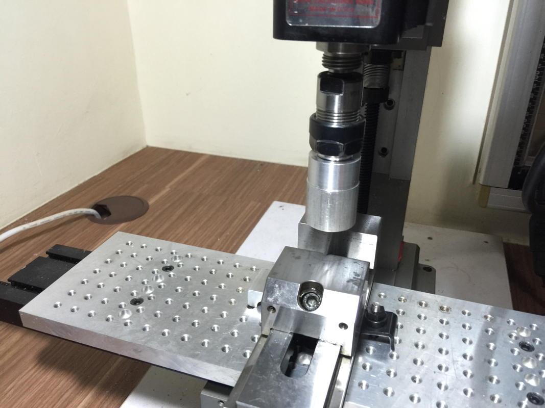
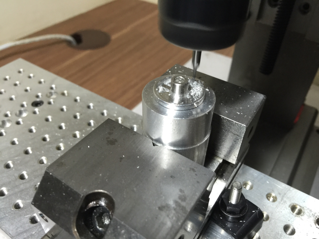
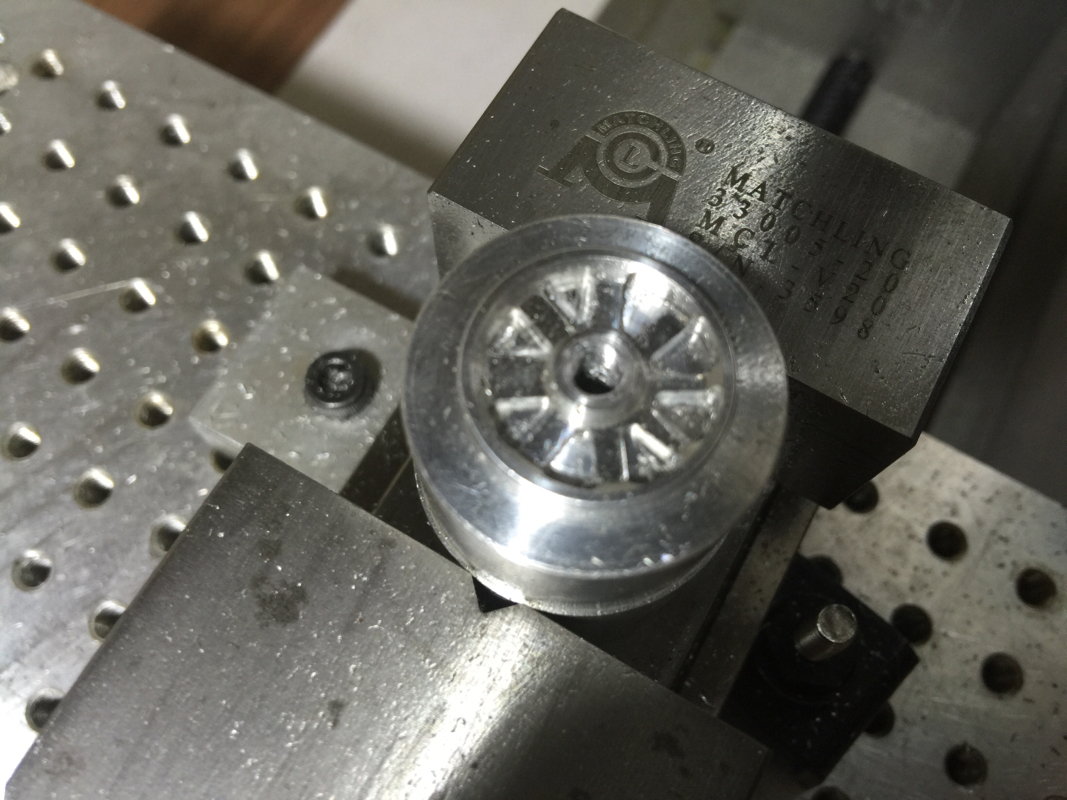
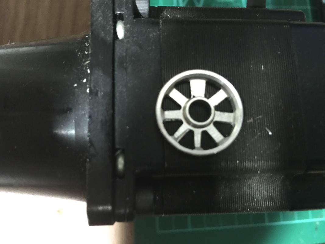
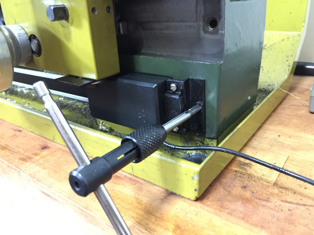
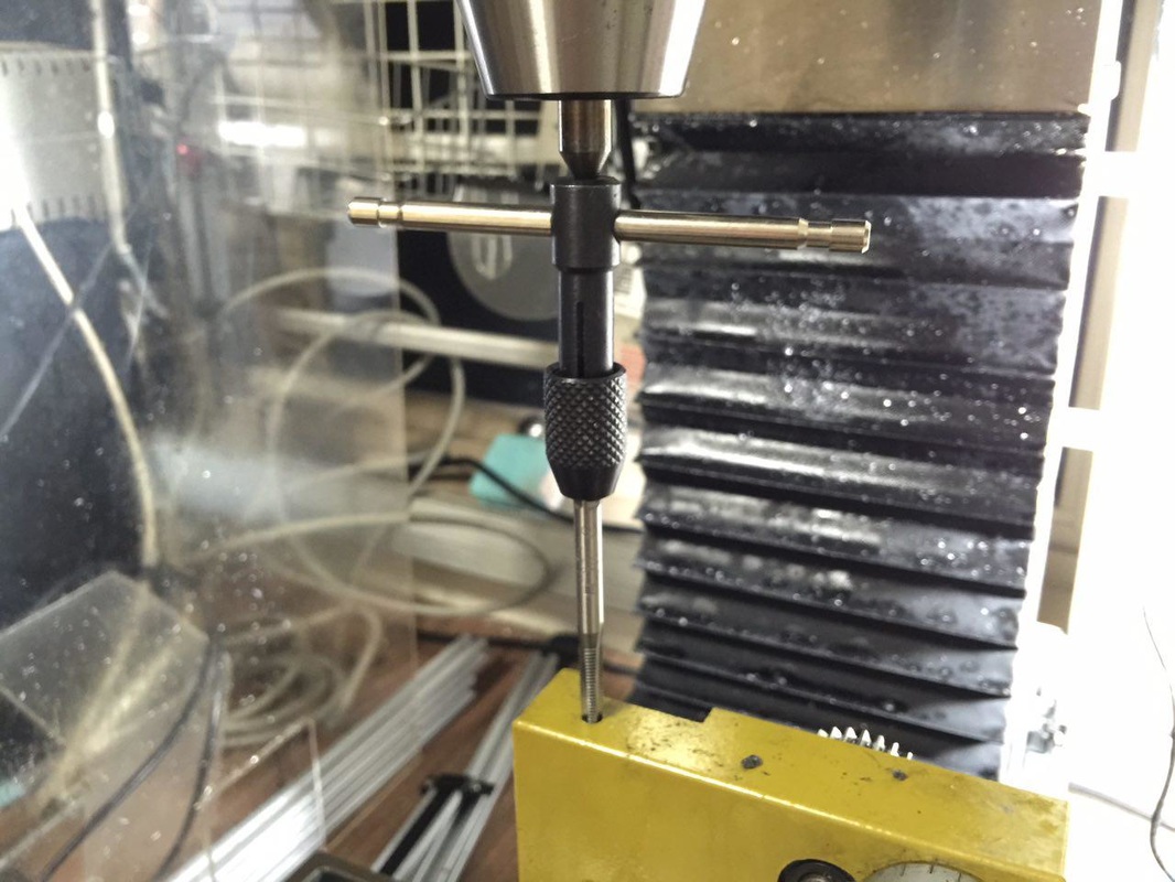
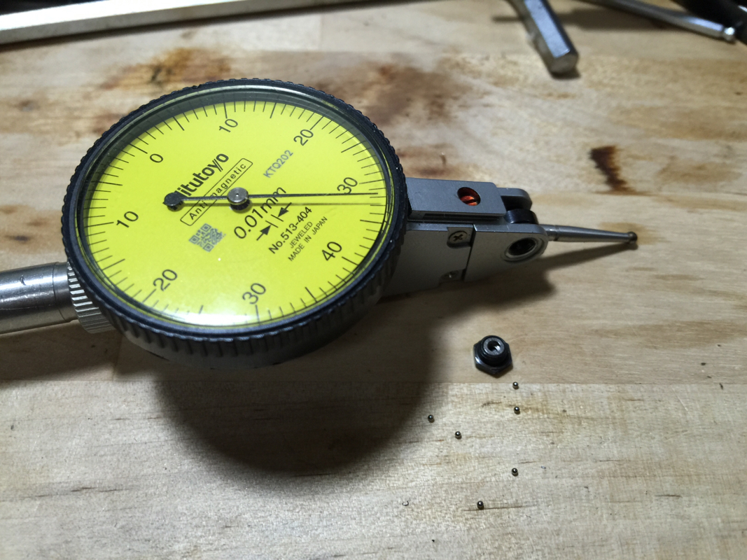
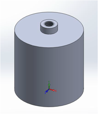
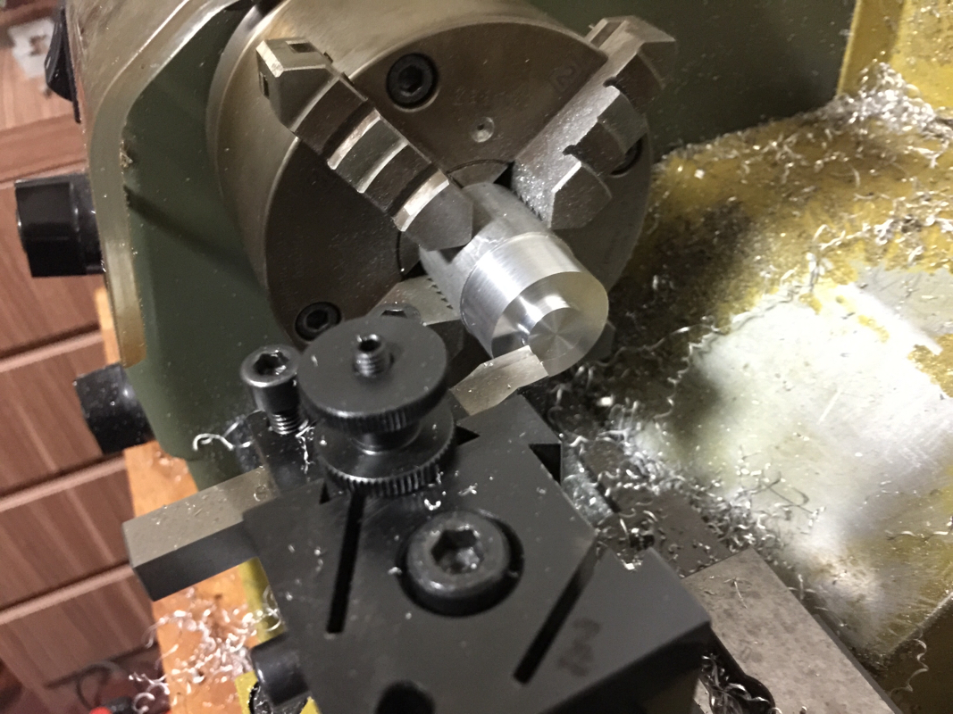
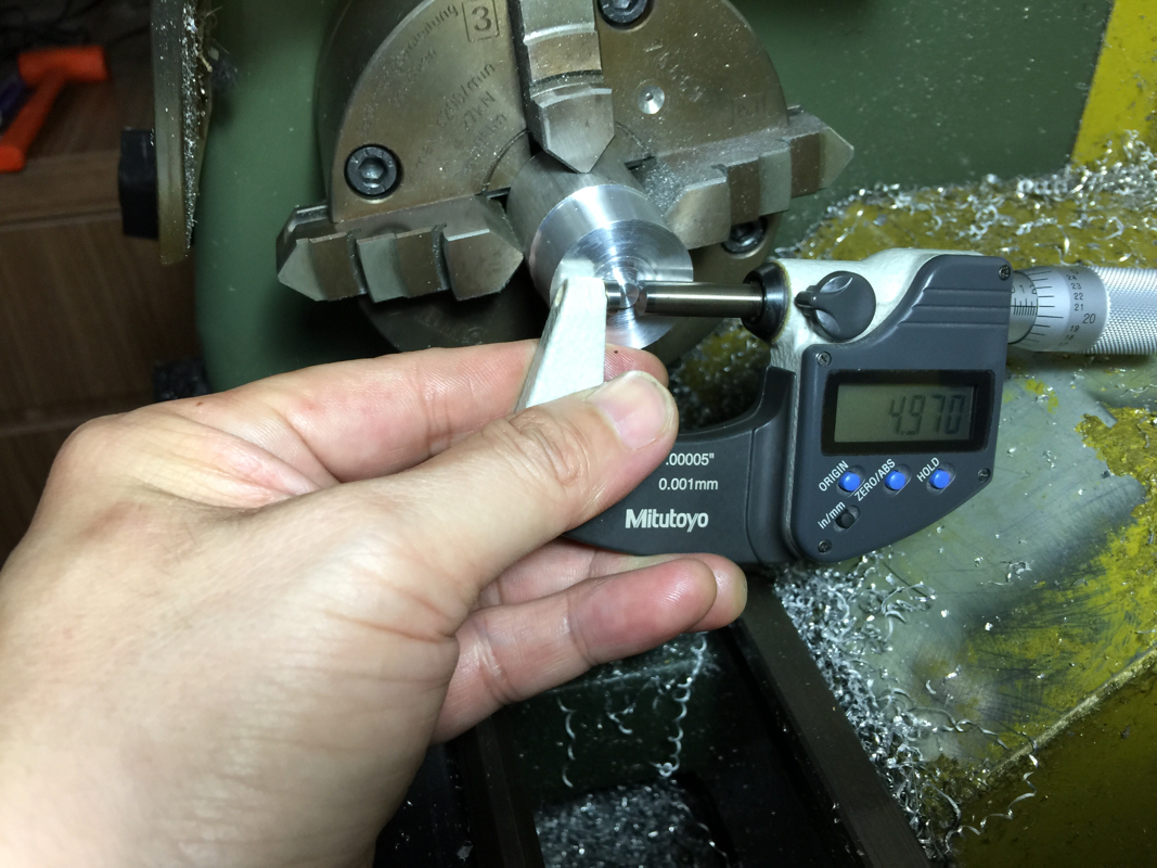
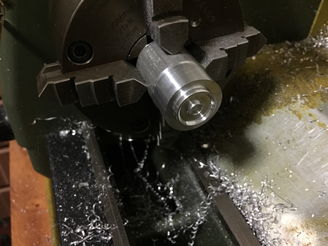
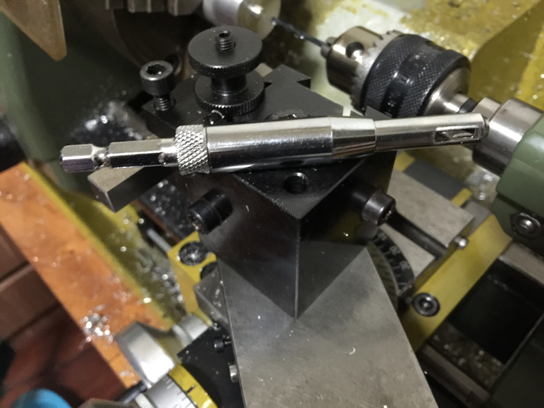
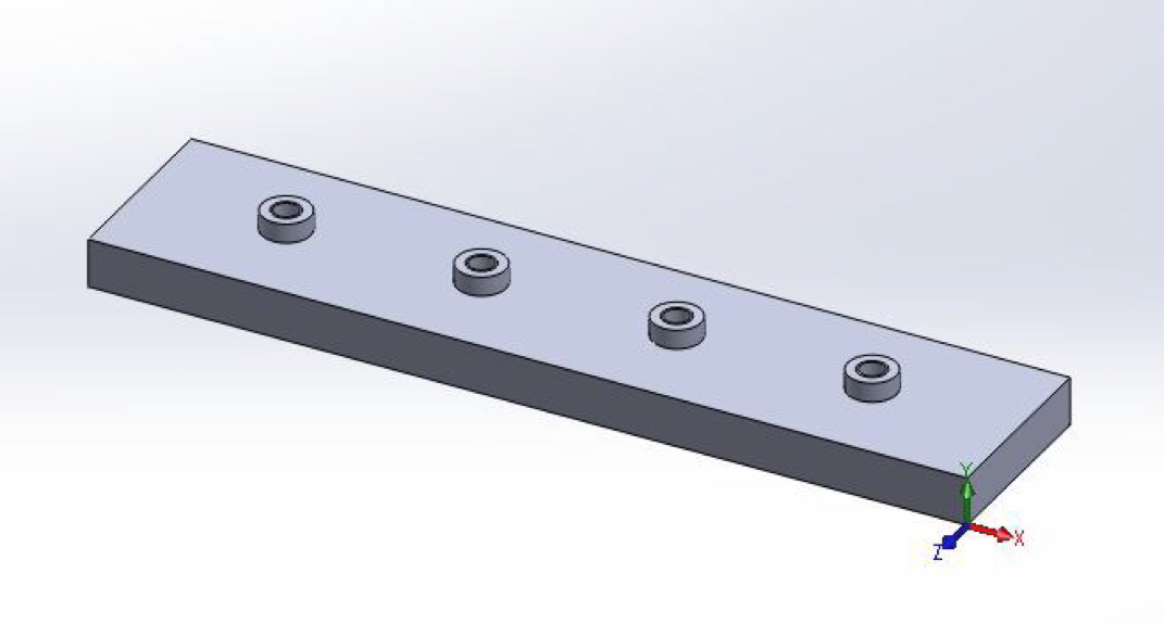
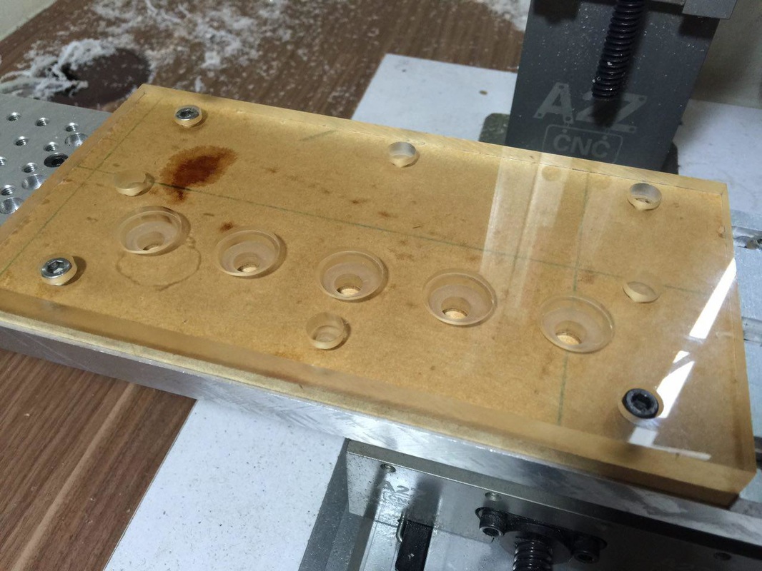 Milled the steps and drill through to tap out the rollers after machining. 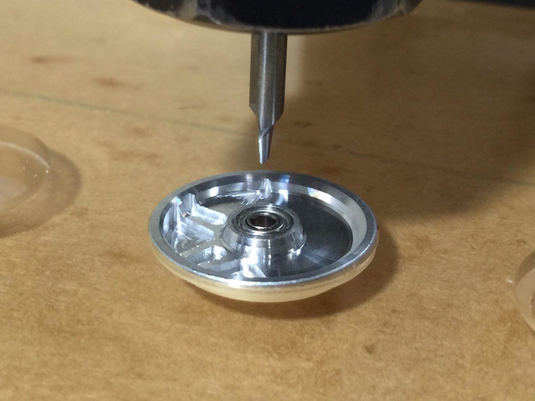 Started milling and broke my 1mm carbide endmill... I've no more in the box and have to get one after the long weekend... 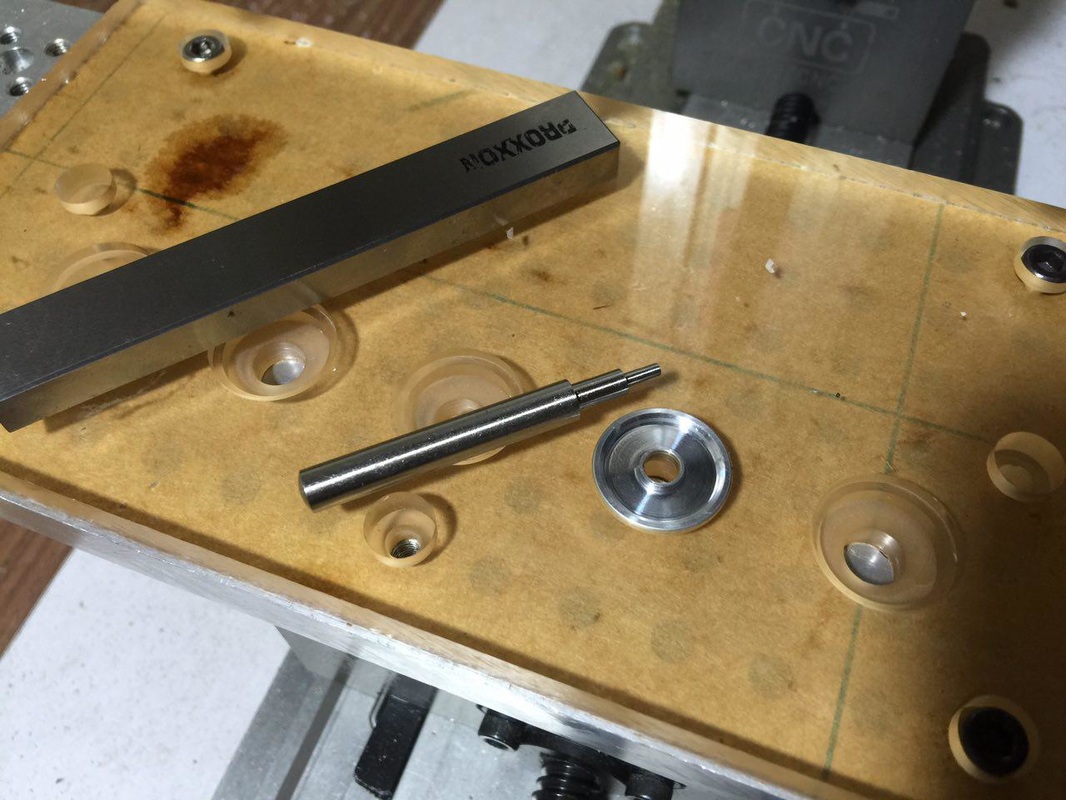 The tip of the stylus is 1.90mm. My trusty Proxxon parallel used as the plate for accurate Z height touch off. 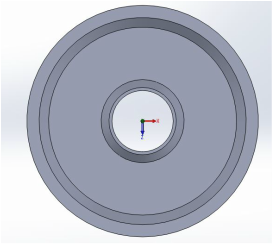 With the measurements, I redo the blank in 3D. 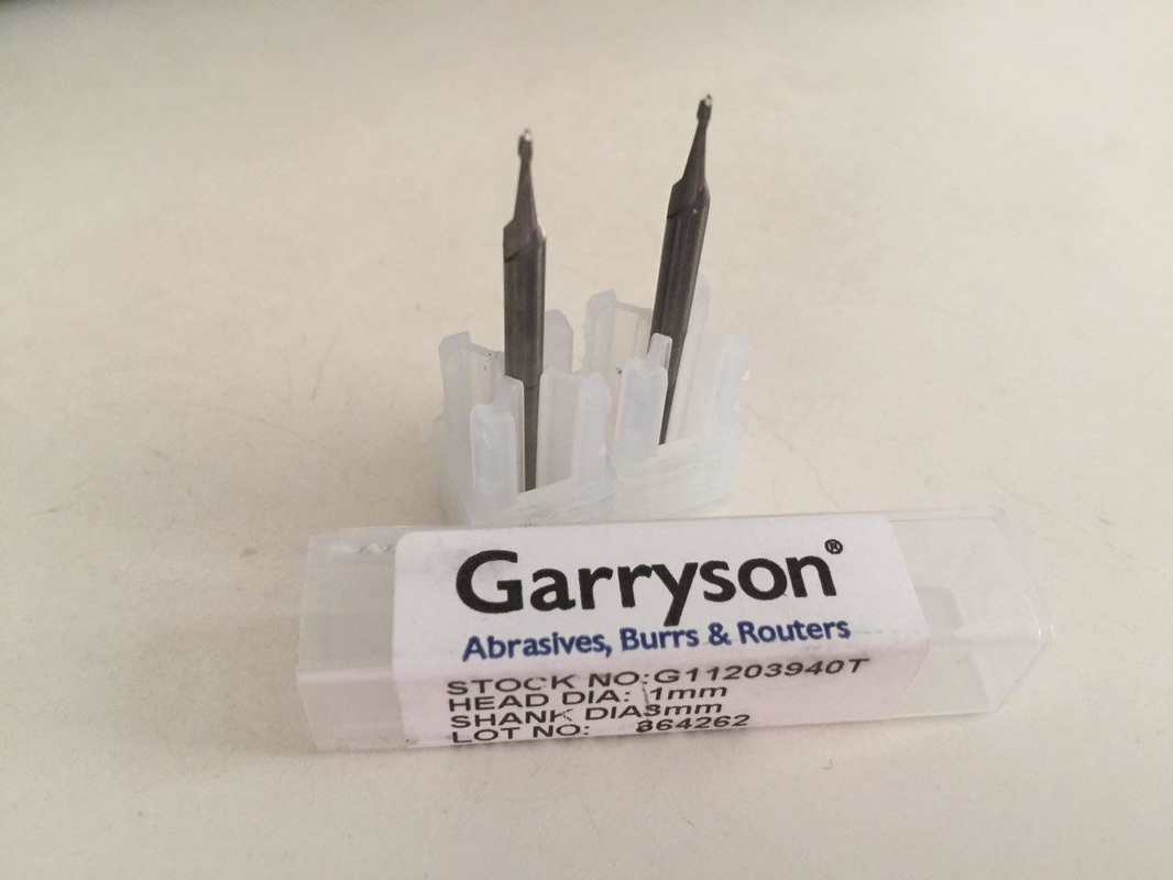 Thank God that Mike opens on Saturday, despite being eve of our National Day! Rushed down in the afternoon to purchase 2 x 1mm carbide endmills. The Garryson endmills are a few dollars cheaper than those Mitsubishi endmills. I bought a 2mm from Horme and paid slightly more than $20 for it. Garryson's was only $16+ inclusive of GST. 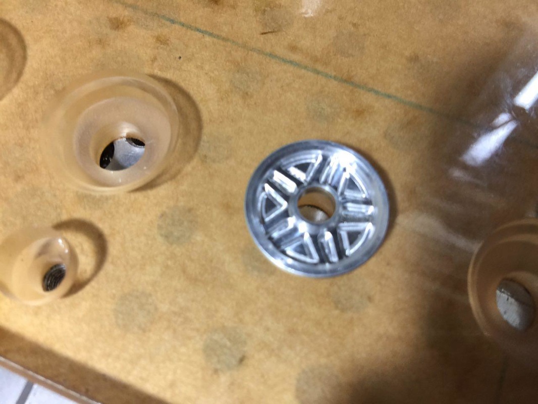 Didn't quite cut through but easy enough to push the unwanted portion out. 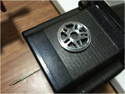 The back before deburring. 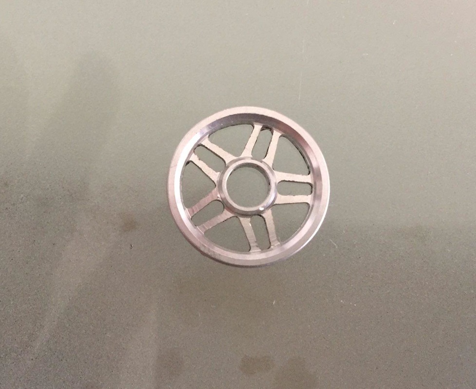 After more deburring. | 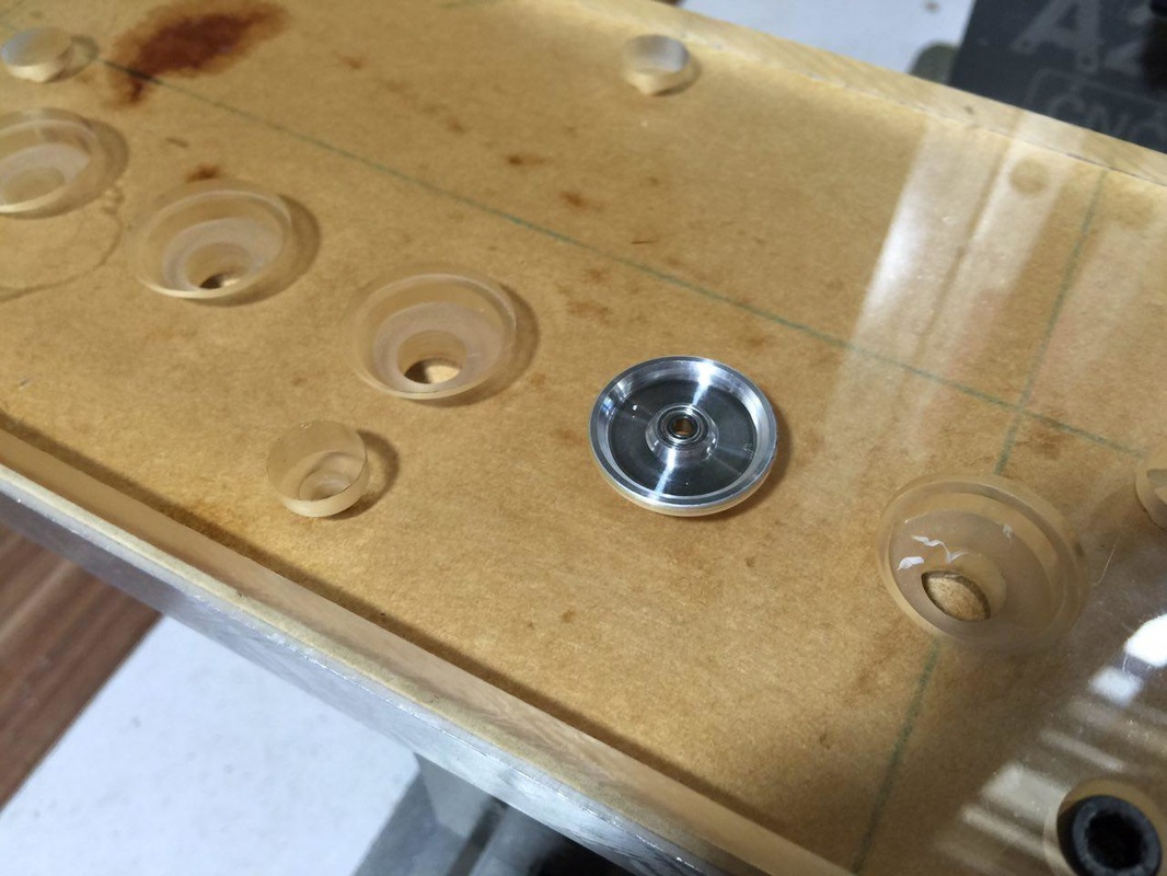 Test fit. Very tight but now I'm able to remove it by lightly tapping from the drill hole. 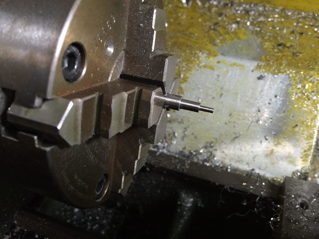 Had some time to spare and so made myself a stylus to help as a touch probe. 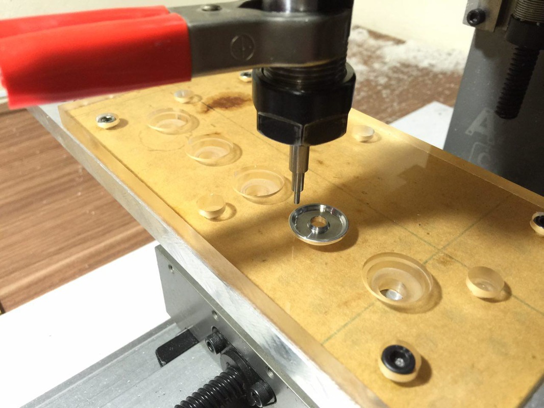 To get the flat land within the 2 chamfers, I first touch off the flat portion, lift Z off by 0.1mm, and proceed to touch off the X axis at the rim and hub ends. 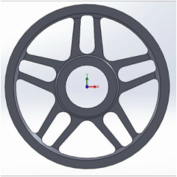 Type 3 based on the new blank in 3D. 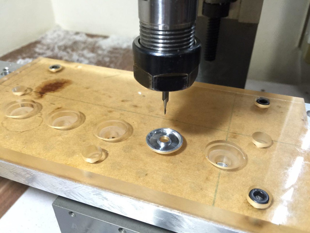 After zero'ing in several times in Z and in the middle of the 5mm bearing hole, I nervously click on Cycle Start. 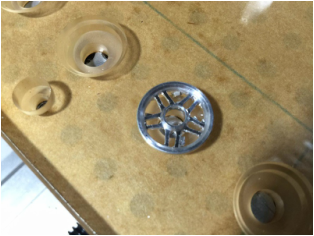 After the unwanted portion pushed out with a screw driver. 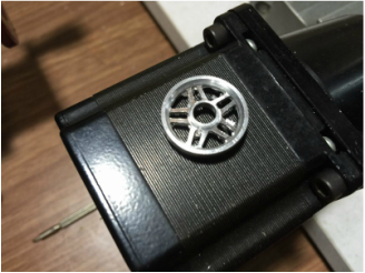 Front 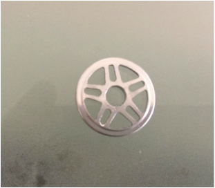 The back looks cleaner... |
It was nerve racking watching the mill went round doing its job. I was so afraid of breaking another endmill. I was told that with endmill so tiny and my max. spindle speed at 2800 rpm, I should go no more than 56mm/min feedrate and at DOC of 0.2mm per pass. It will be painfully slow... For this roller, I went at 100mm/min instead. It turns out well except having to spend quite some time deburring the tiny spokes. With my "old flower eyes" (long sightedness, started when I crossed 40...), it was painfully difficult.
Next up, upgrading the Sherline to 10,000 rpm pulley.
Next up, upgrading the Sherline to 10,000 rpm pulley.


 RSS Feed
