Wongster's Production
Share it on
  • Home
  • Blog
  • My Old Blog
  • My Shop
  • Resources
  • About Me...
  • Contact Wongster

Practicing On The Lathe

25/7/2015

0 Comments


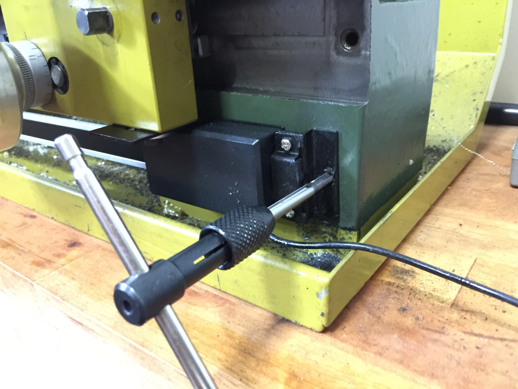
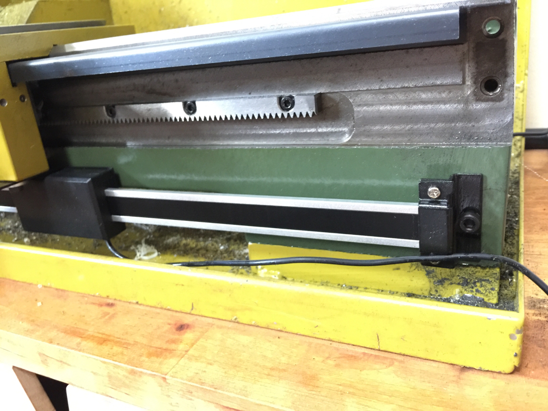
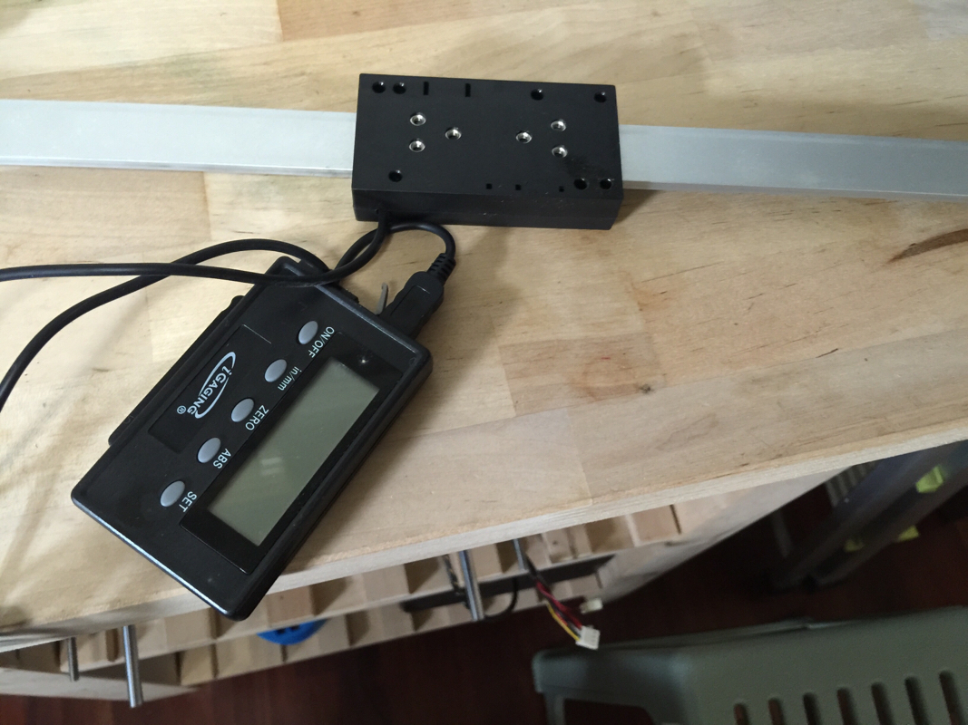
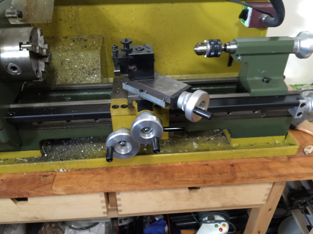
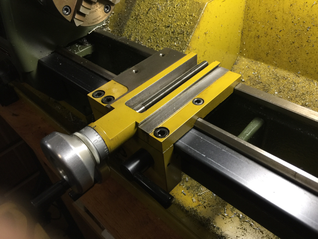
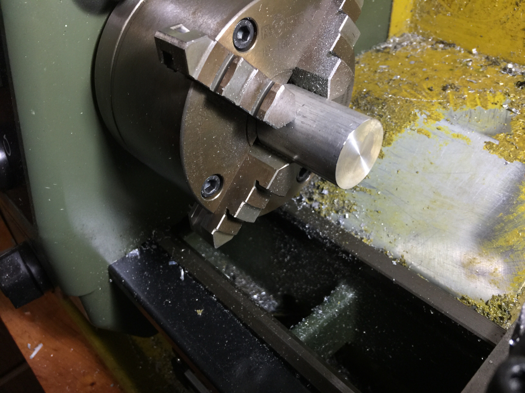
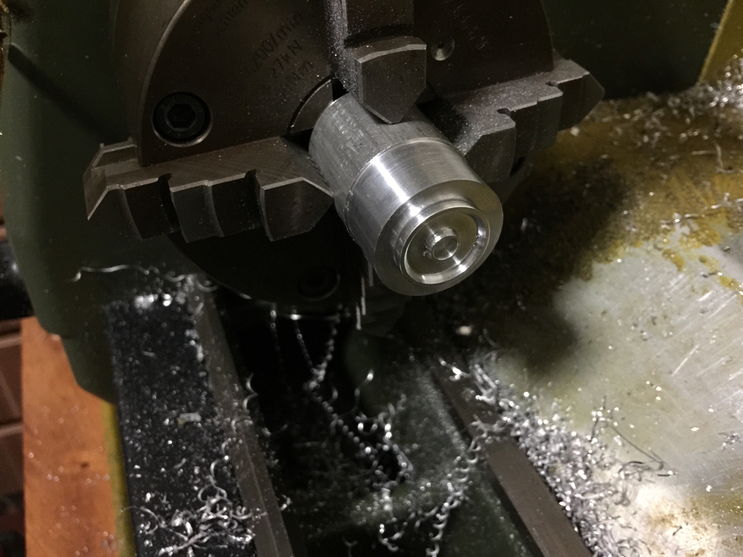
It has been a while since I do any serious work on the lathe. After fixing up the scale, the carriage was reinstalled and I took some time to take out some slack in the hand wheels and the screws. Turning is a little tighter now but still rather smooth. To get a proper feel, I chuck up a small piece of aluminum and did some test.

Picture
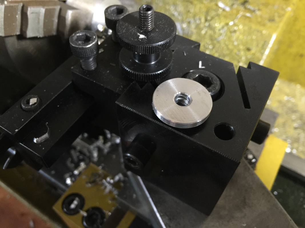
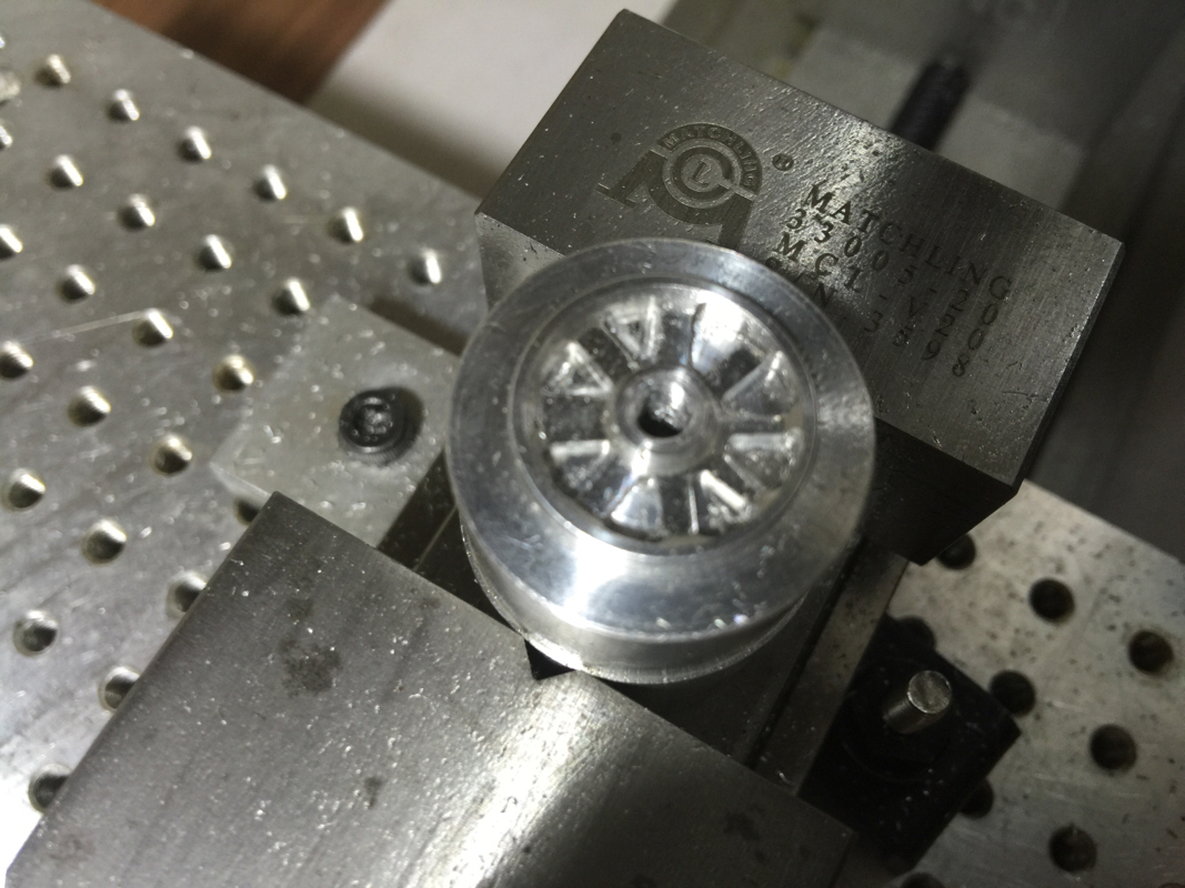
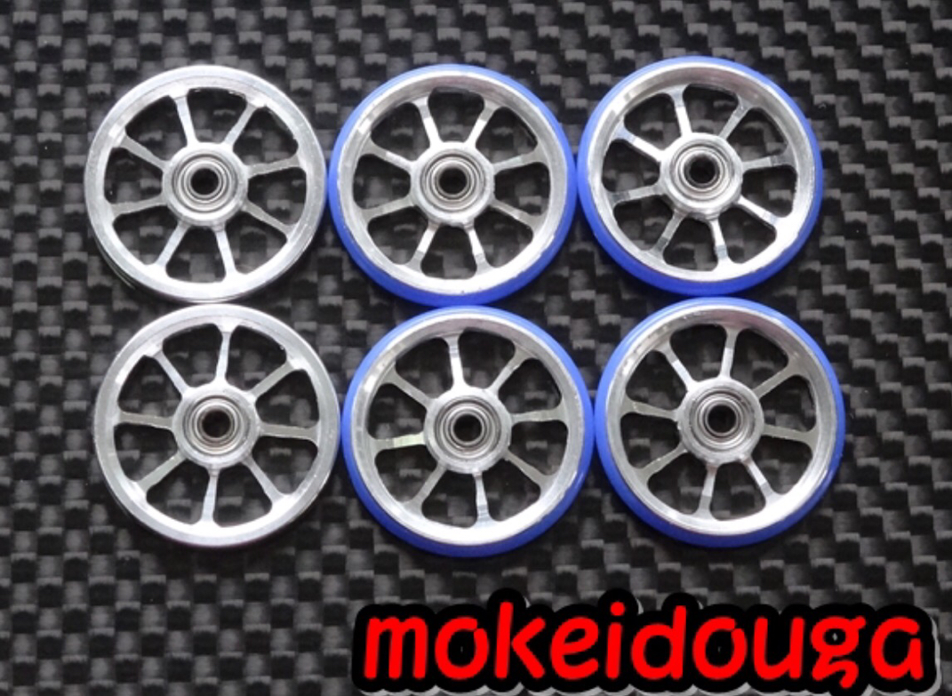
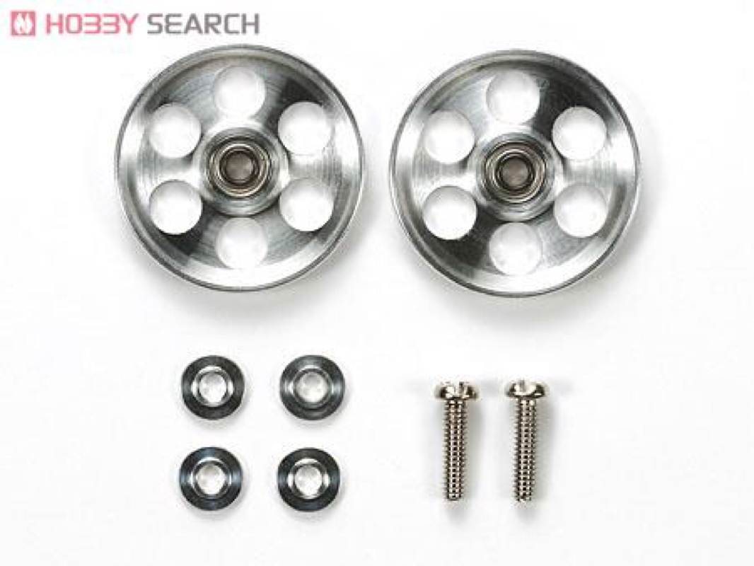
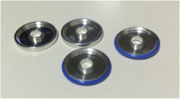
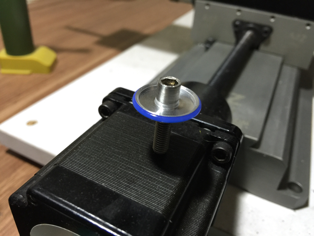
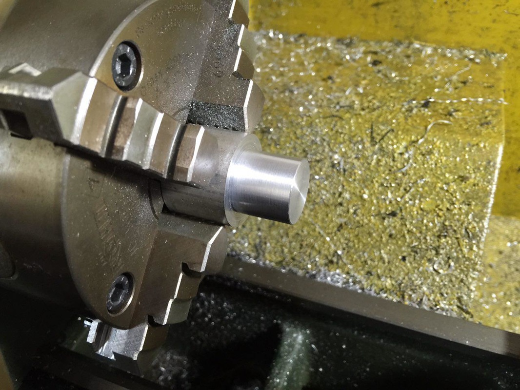
The target diameter is 19mm, which is the size given to me for the slot car roller.
Picture
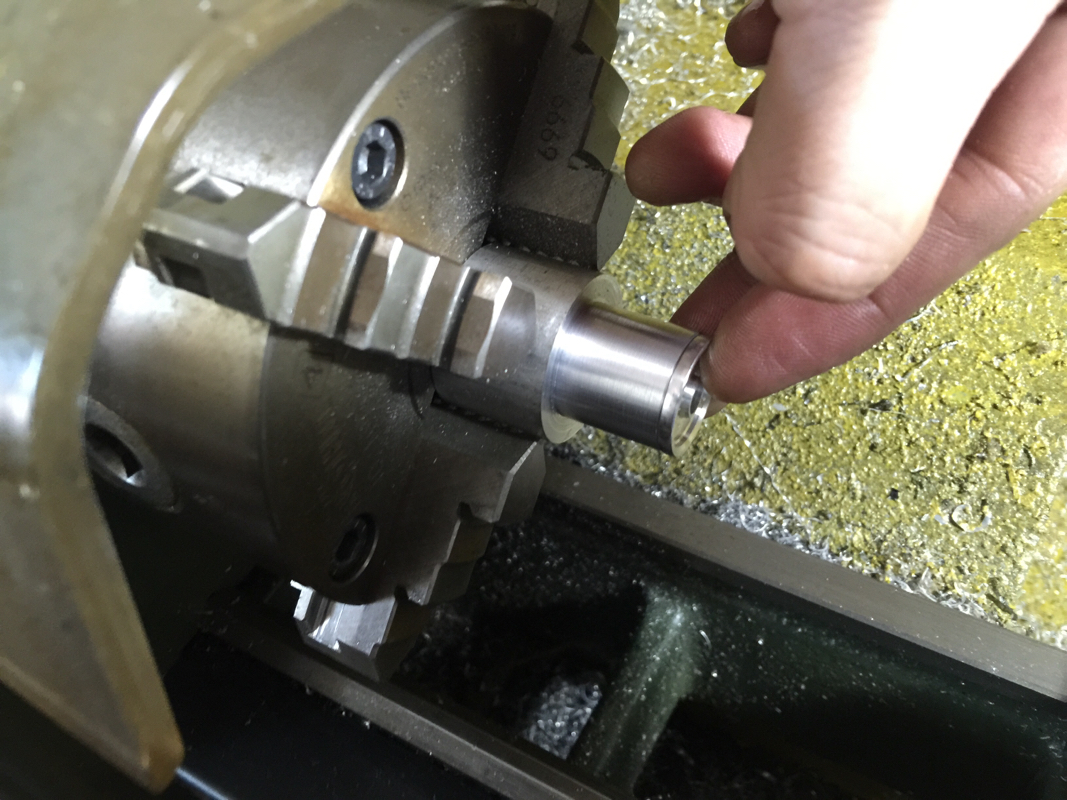
Putting the roller on the workpiece for comparison.
Picture
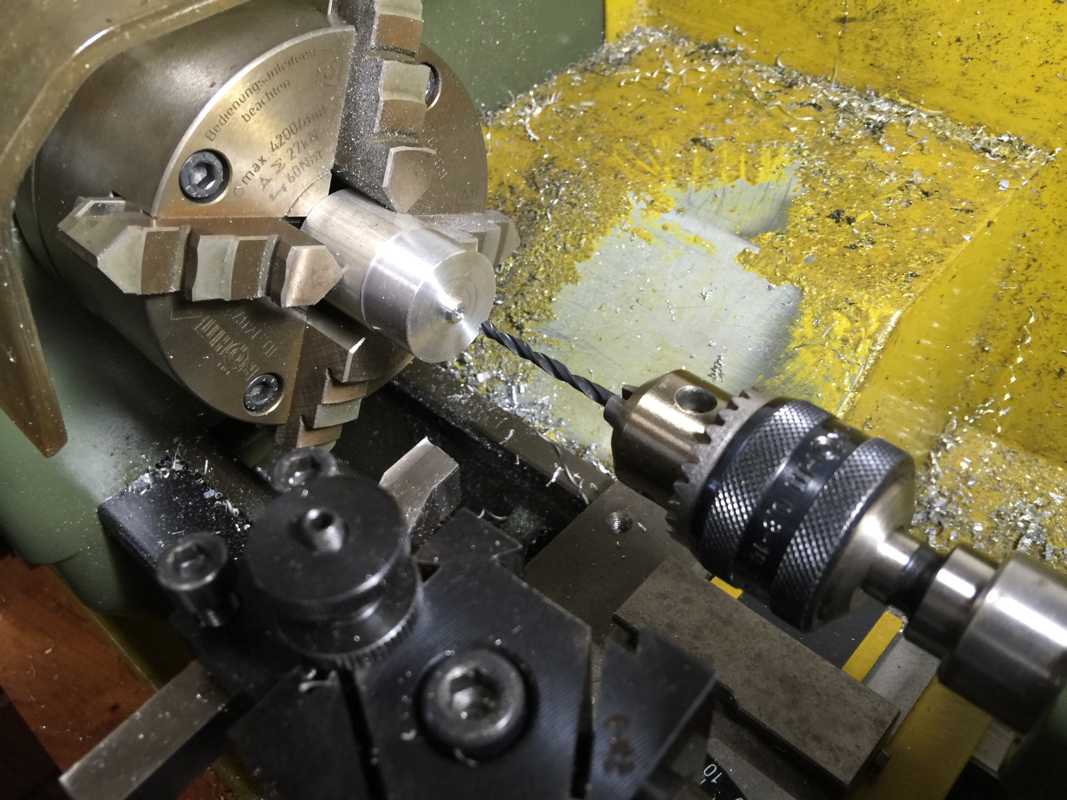
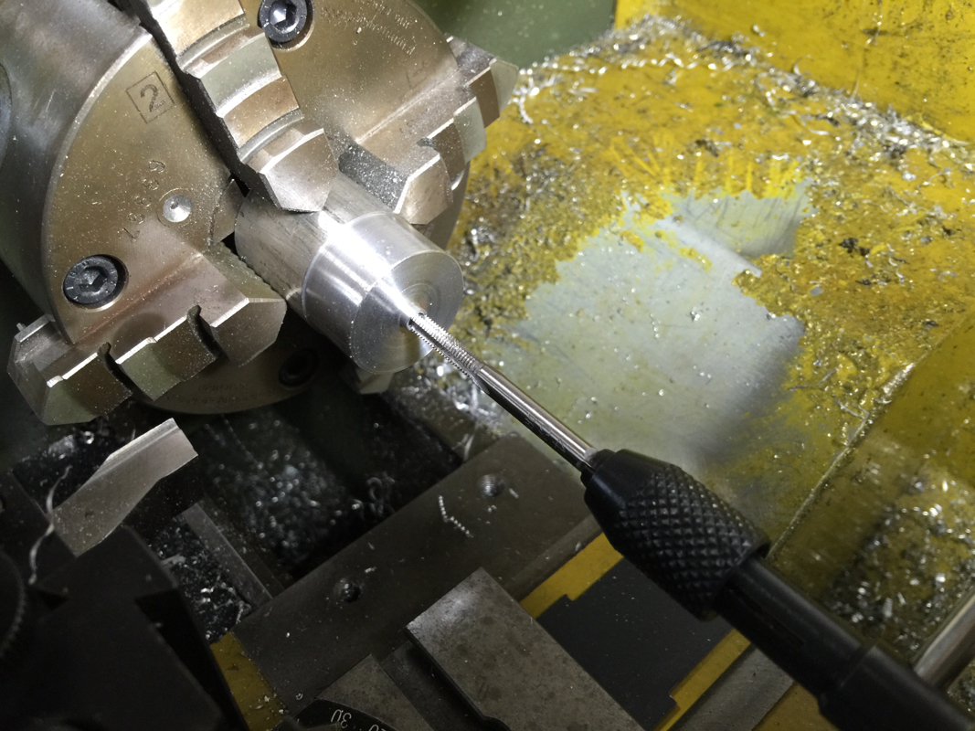
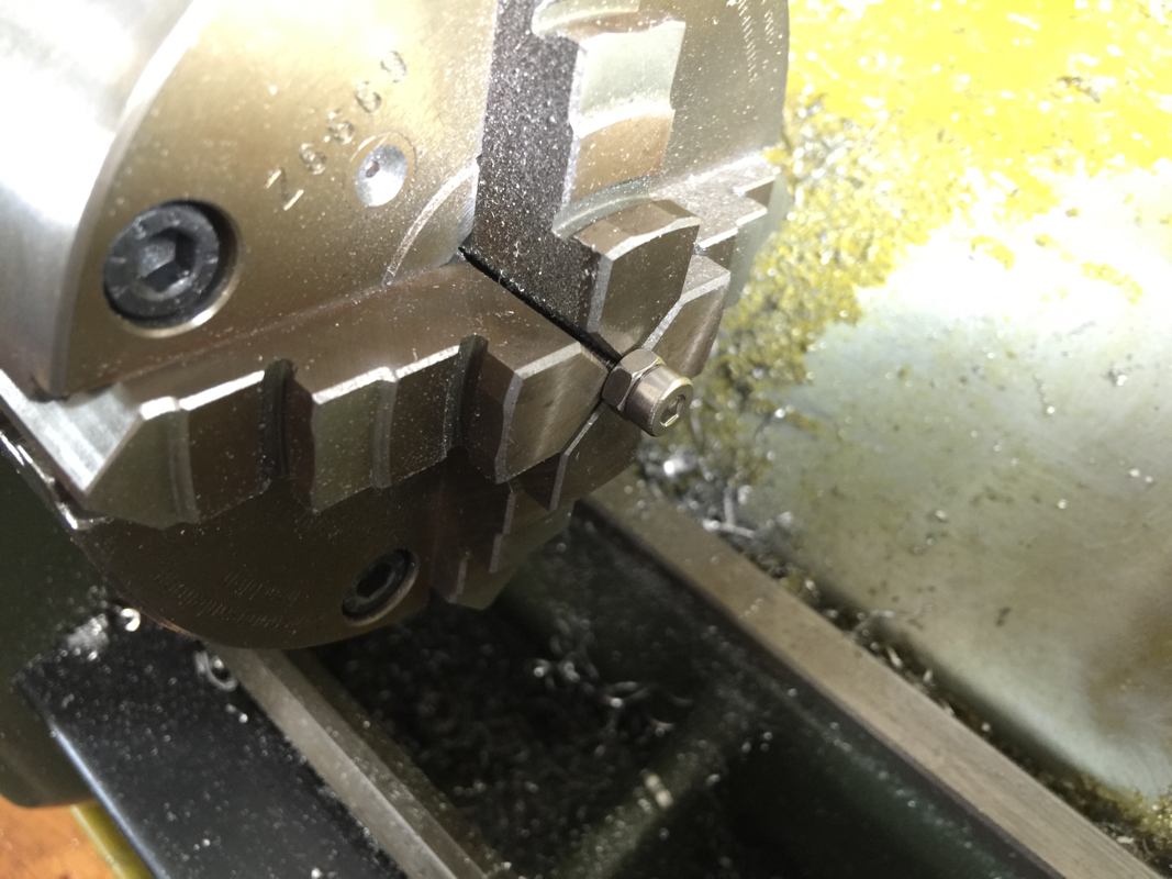
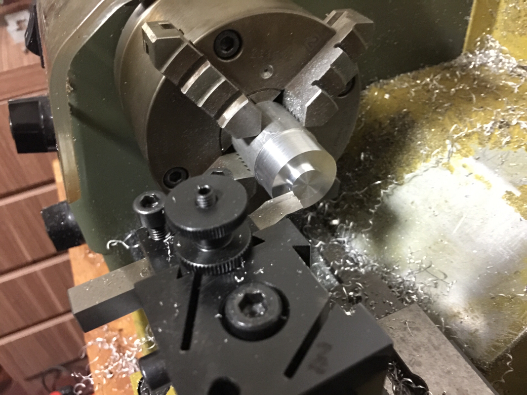
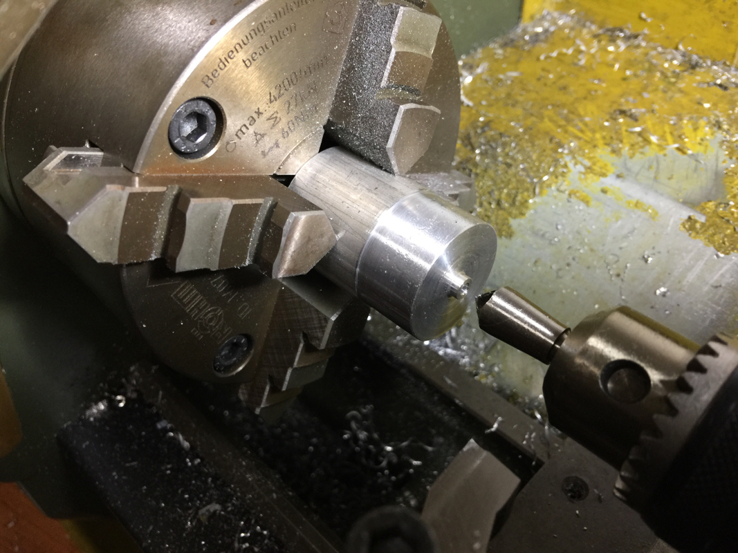
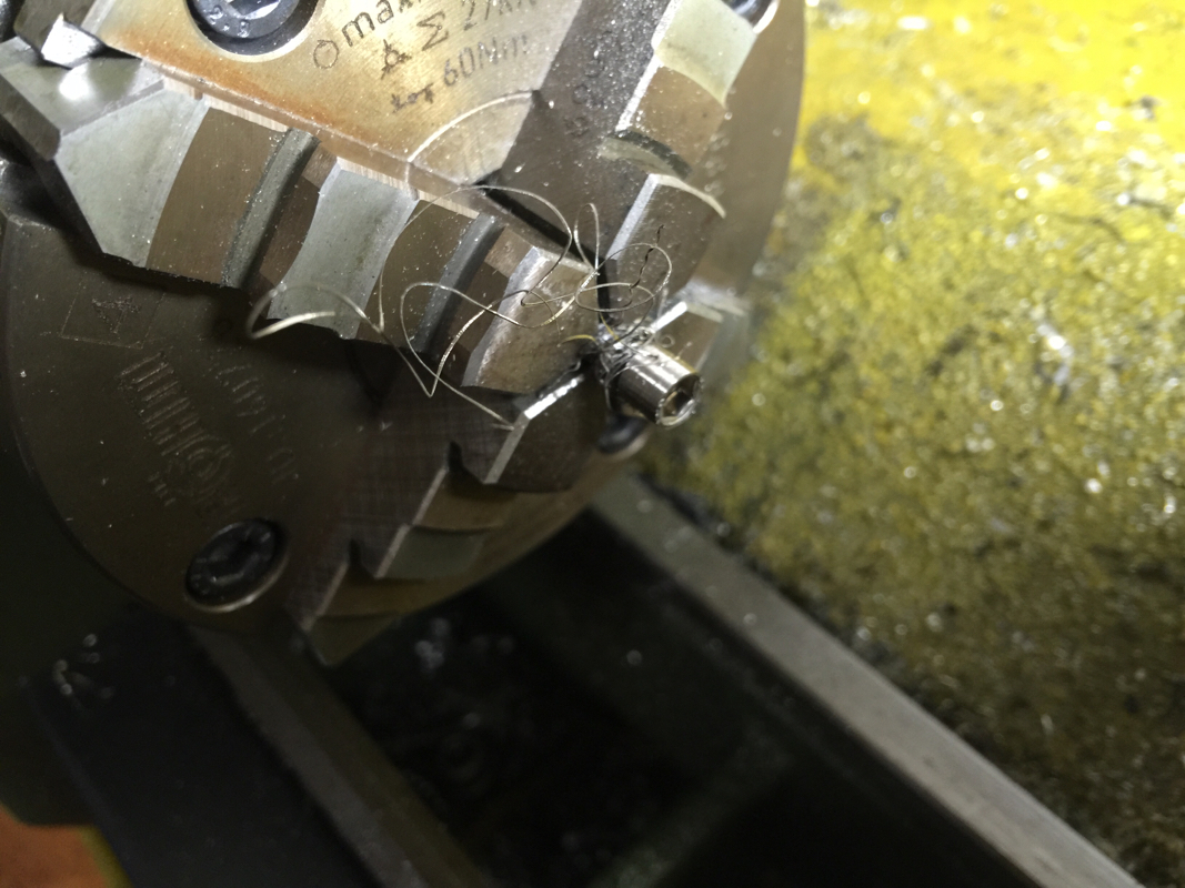
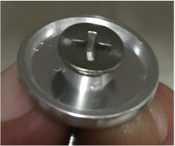
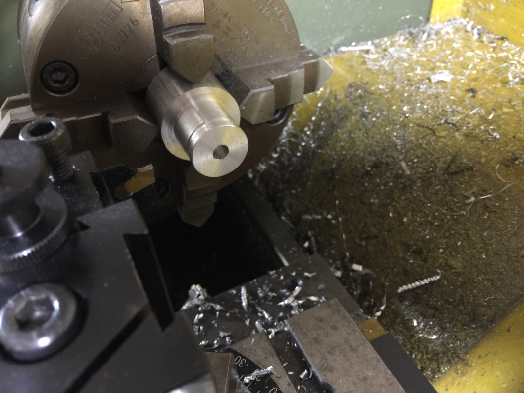
Just when I started parting off, I realized that I forgot about the 5mm hole... Was too eager to try out using the DRO. Not too late to do the drilling though.
Picture
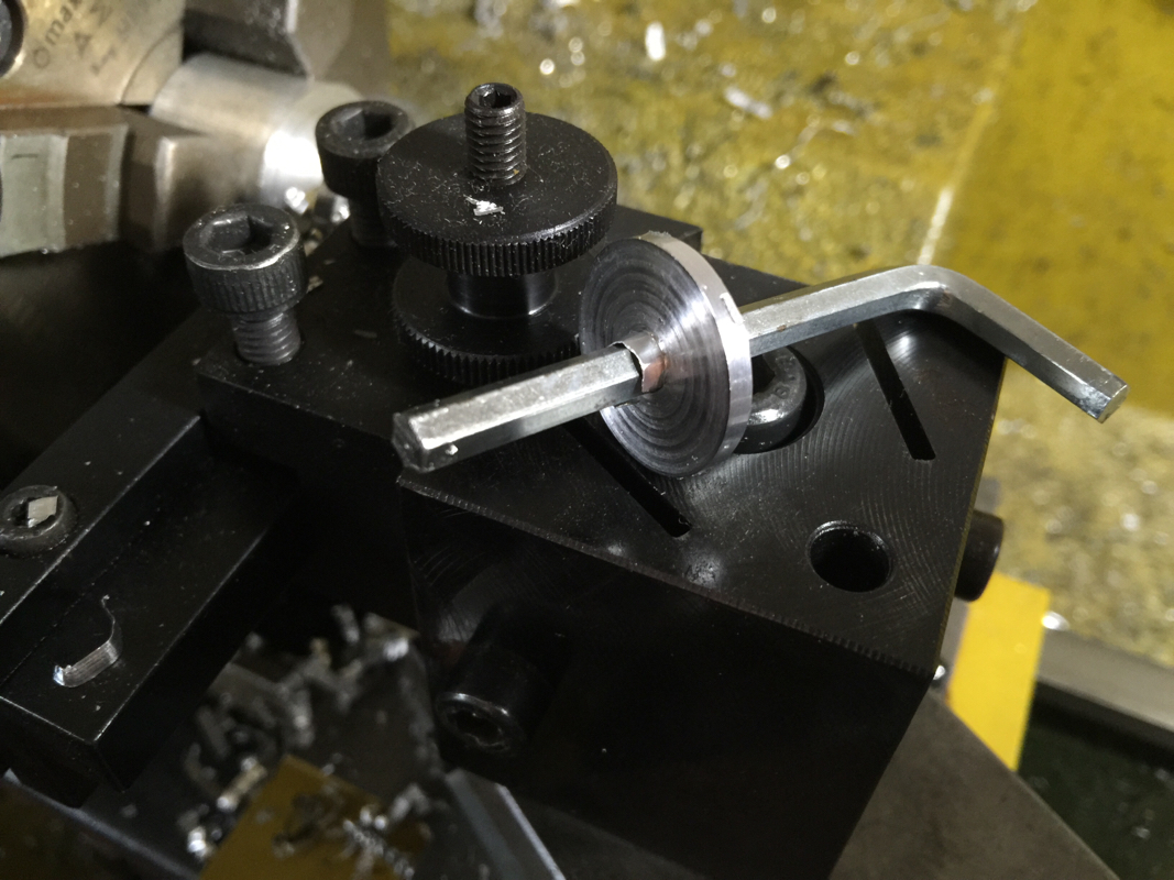
Parted off at 2.36mm. I've to devise a way to hold the cut off piece to face the other side.
Picture
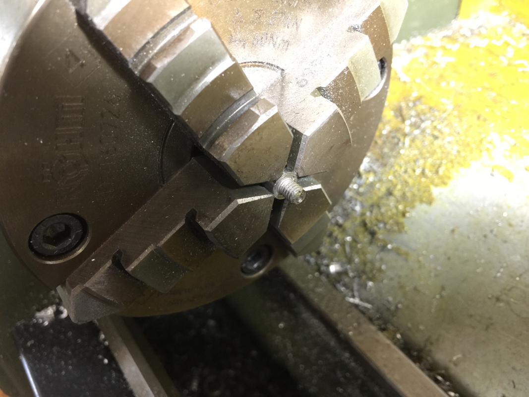
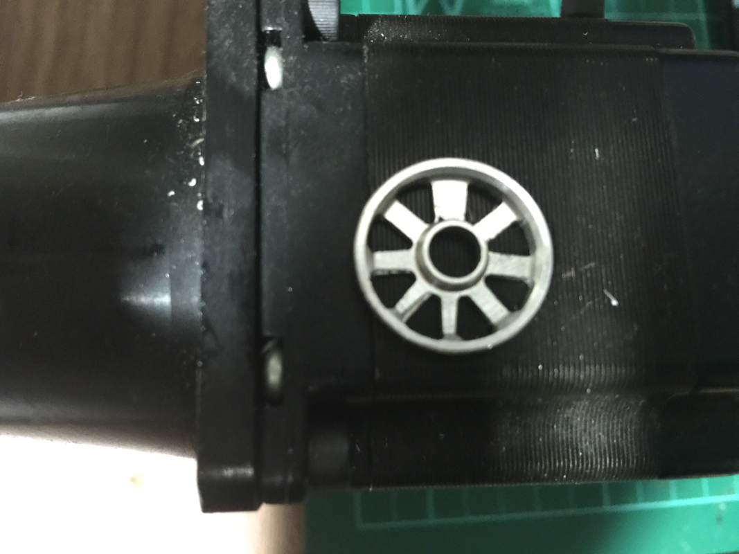
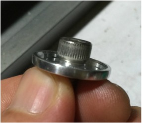
The wheel blank half done.
Picture
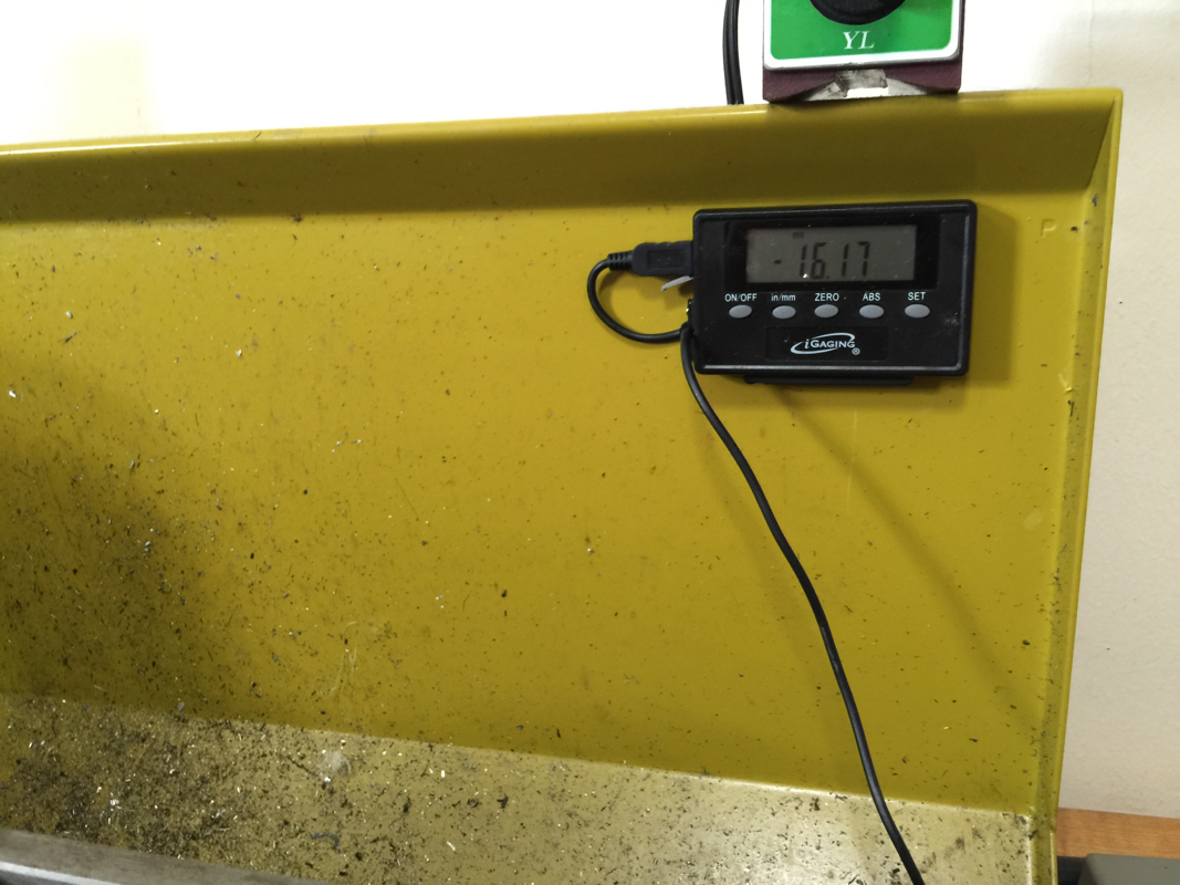
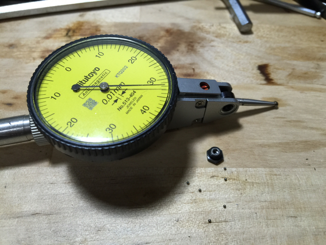
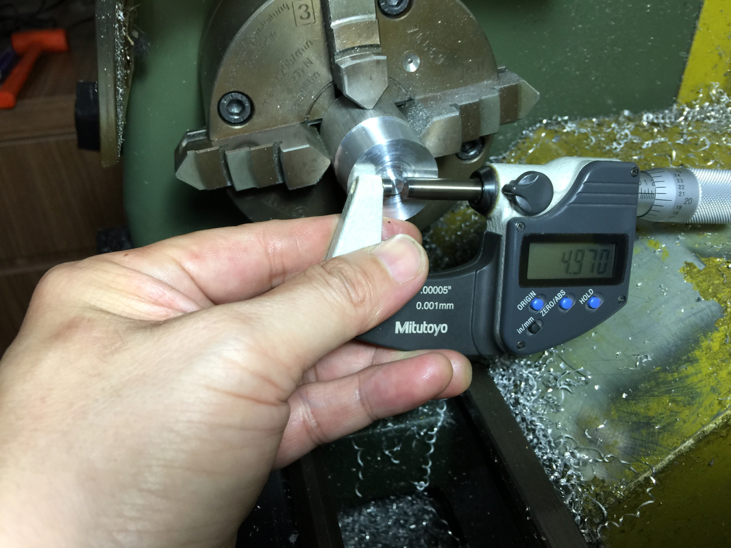
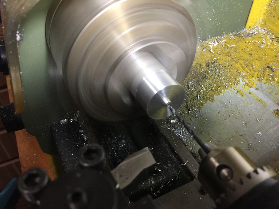
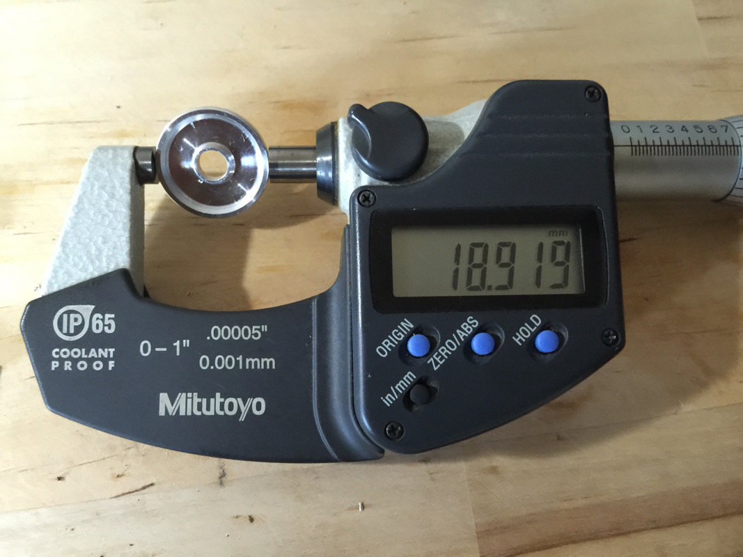
The piece given to me as sample measured 18.919mm. I believe the seller meant it to be 19mm (per their website) but this is not a part that requires tight tolerance.
Picture
Love to see this: I'm within 0.01mm!

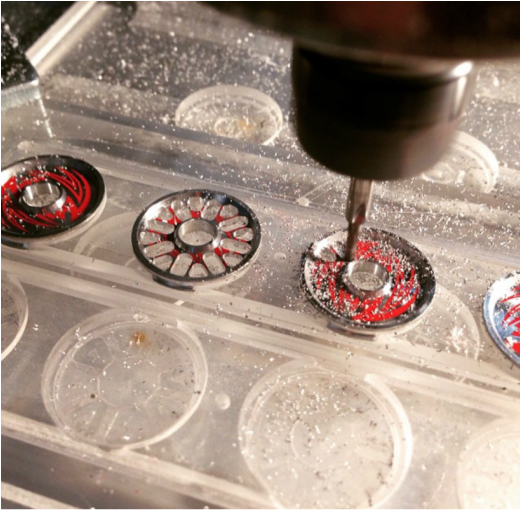
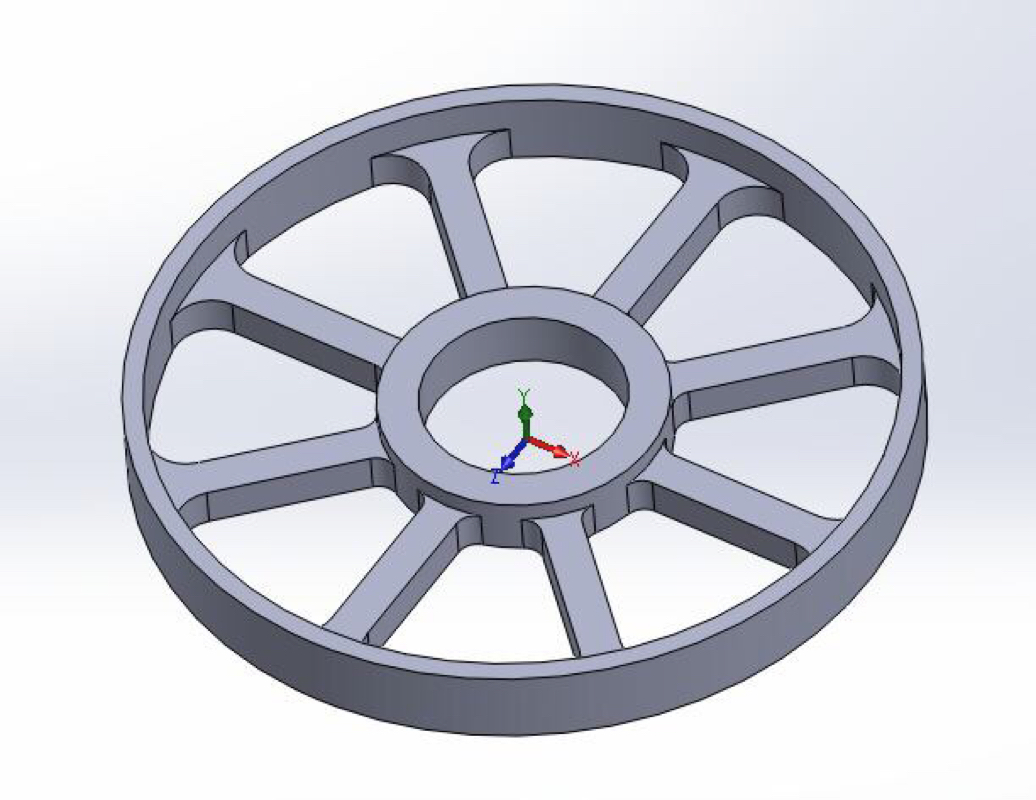
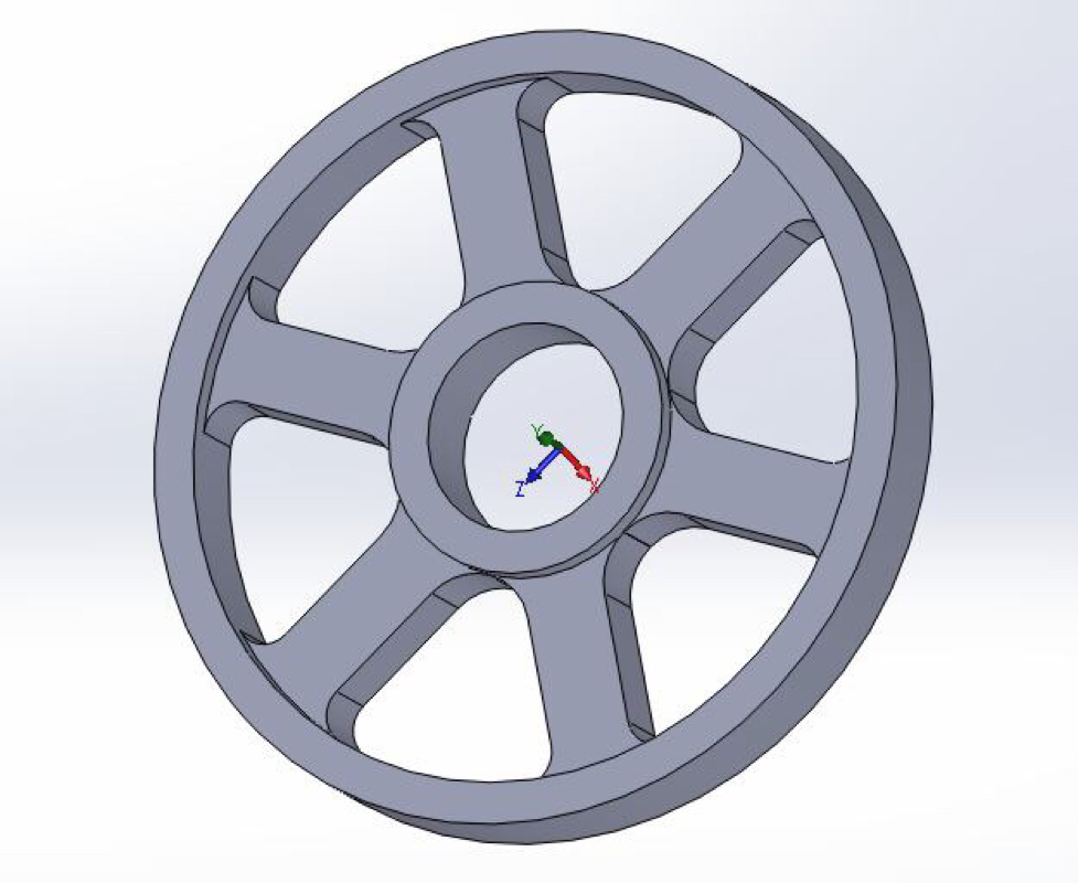
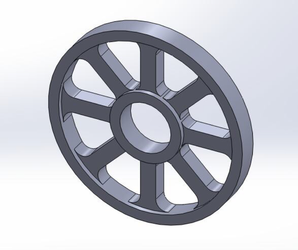
Come to think about it, if I'm to make the wheels from scratch, I don't really need to face off the part off side of the wheel.  Reason being, most of its face would be recessed and spokes milled out.

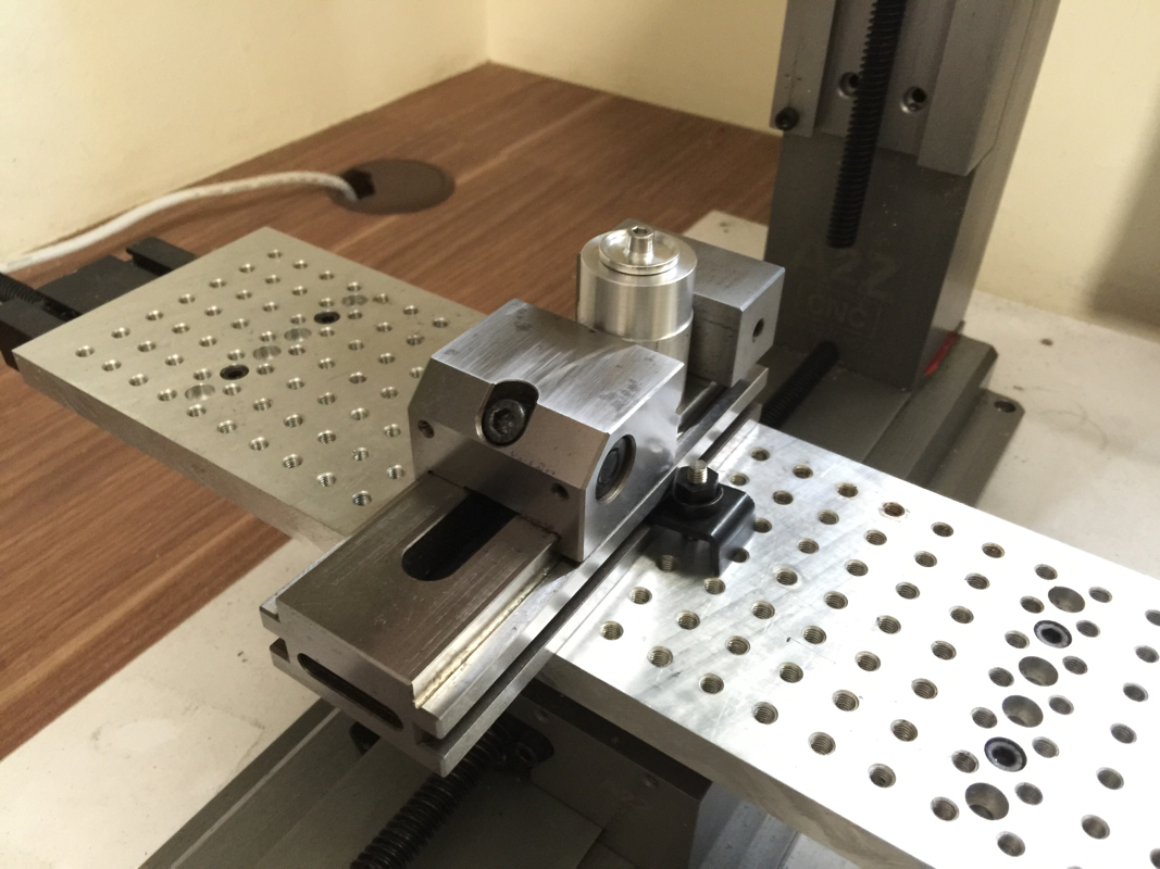
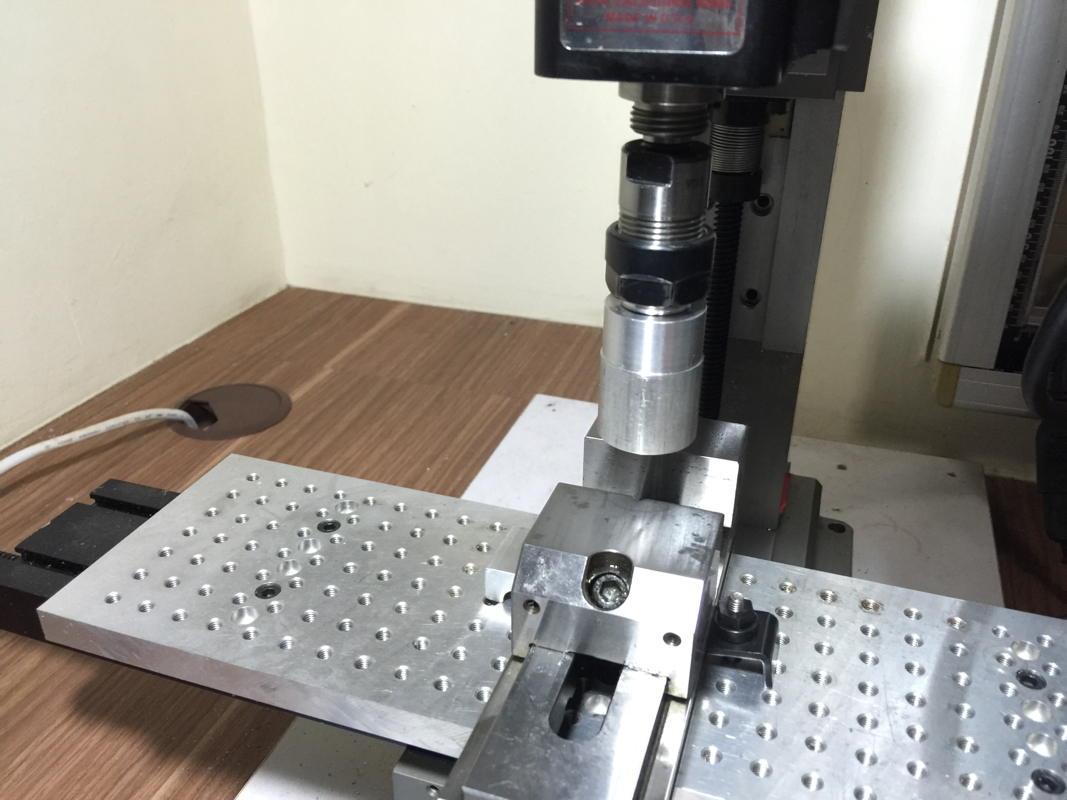
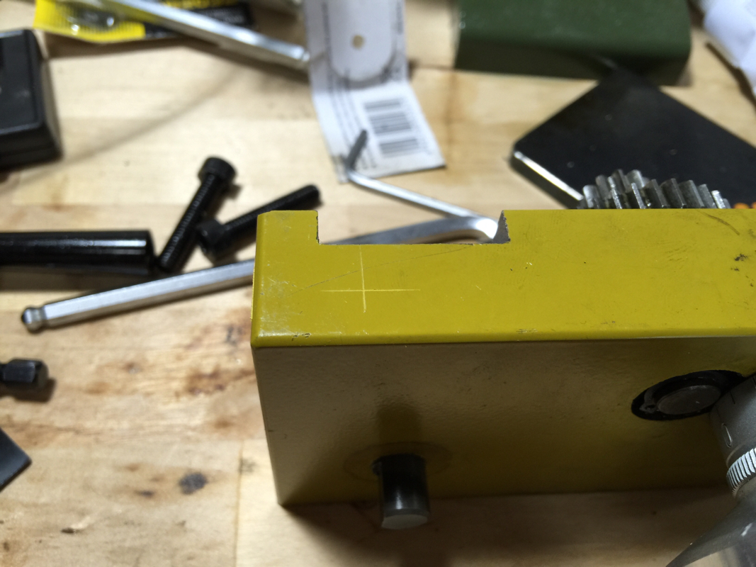
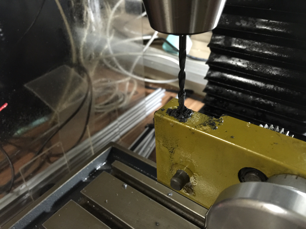
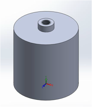
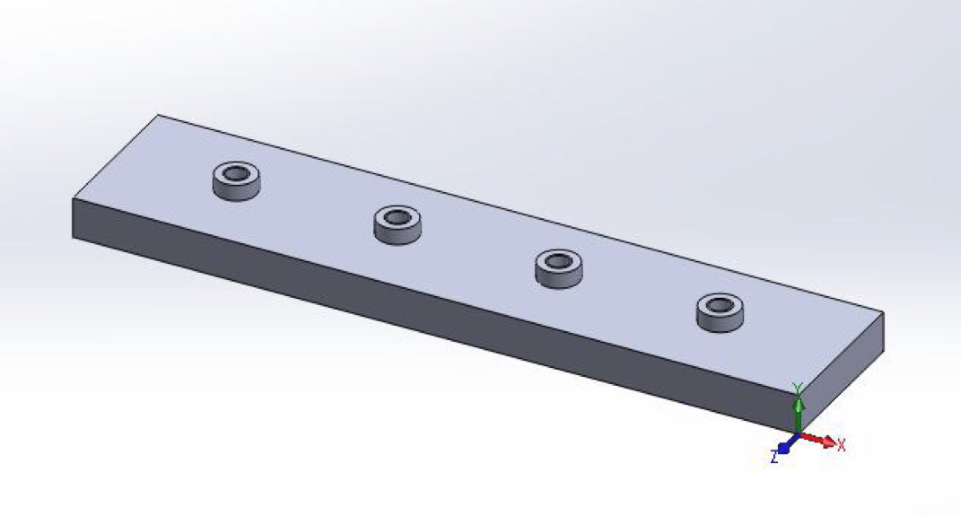
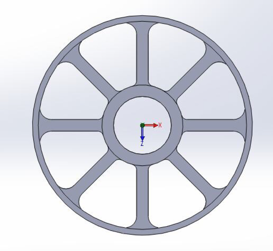
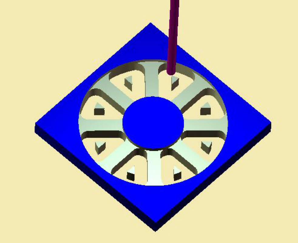
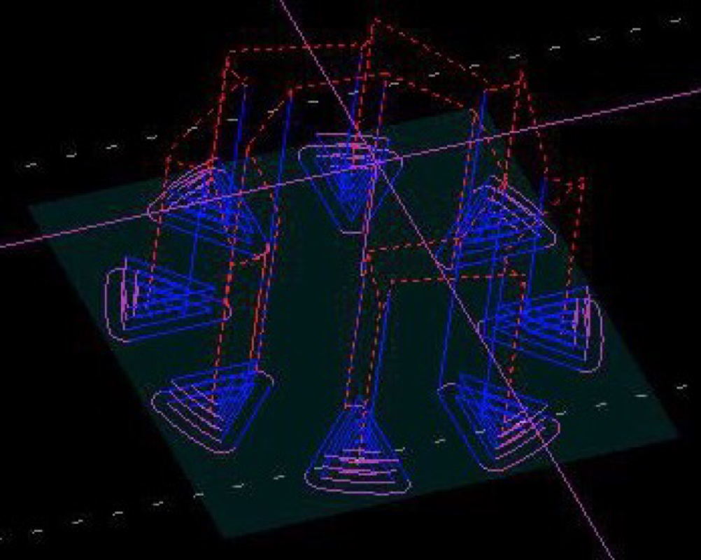
I'll make a wheel fixture to hold the wheel on the Sherline/A2Z CNC Mill.  The fixture will be held in the vise.  This is what I've in mind:

Picture
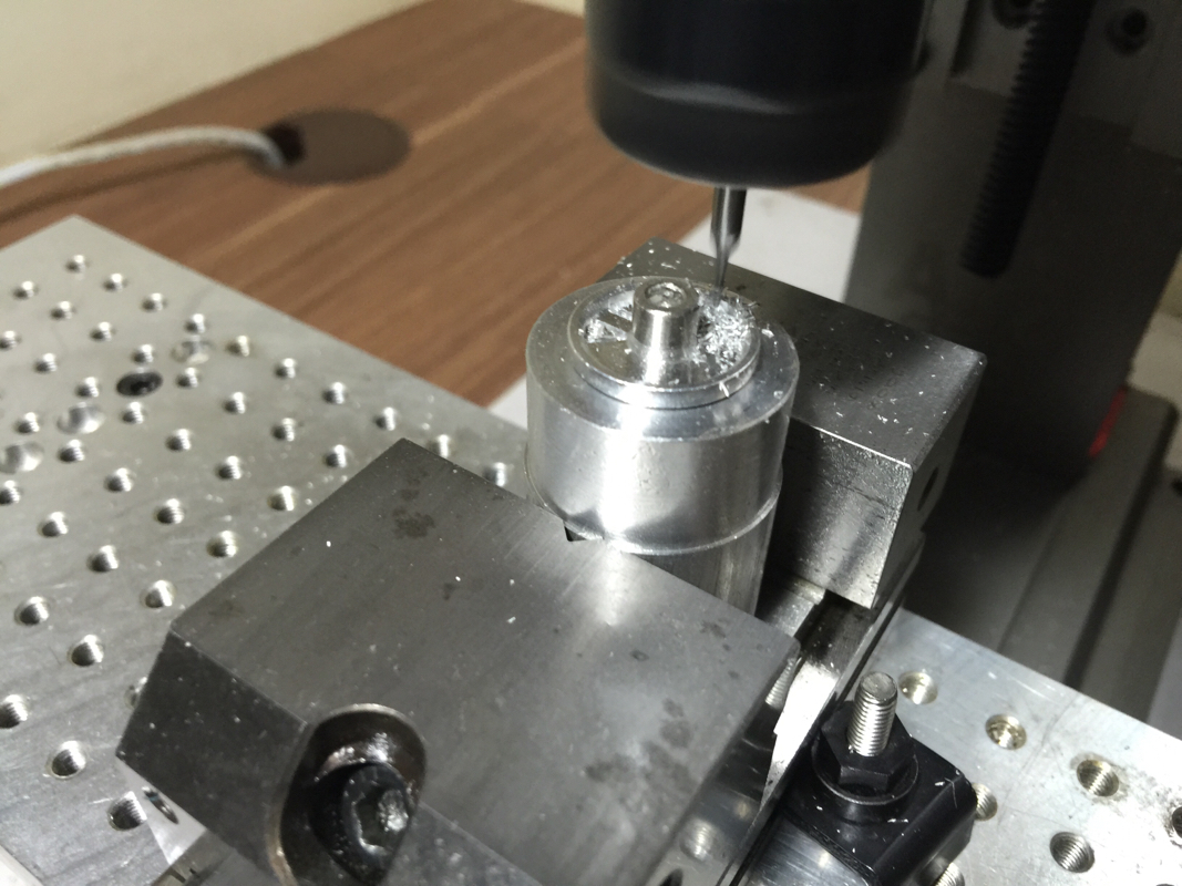
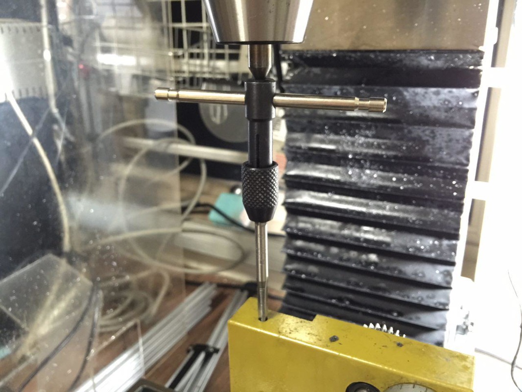
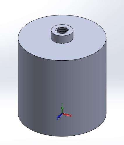
The diameter of the cylinder will be 20mm. The little protrusion on the top face will be 5mm, matching the ID of the wheel blank. It will have a height of 2mm, slightly shorter than the thickness of the blank to hold down the blank. The centre hole will be tapped M3.
Picture
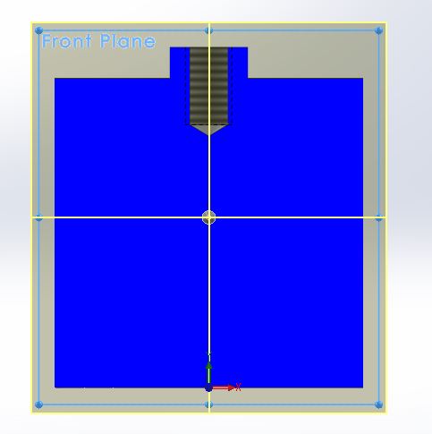
Cross section view of the fixture.

Do let me know if you have any suggestion or spotted mistakes.  I'm still very much a newbie though I've had my machines for 4 to 5 years.

Until next time... be greatly blessed!

0 Comments

wheel Roller - First Attempt - Failed

24/7/2015

0 Comments

 
I spent the afternoon in the shop after I decided to tap the centre hole of the fixture M4. The fixture was completed quickly and I moved on to work on the M4 screw to fit the task.

Being off the CNC mill for so long, I was a little wary. Went through the BobCad simulator several times before committing to the job. The GCode was transfered to the workshop PC, which is still running Windows XP.   After painfully setting up the work and checked through several times again, I hit cycle start... Midway through the program, I saw something that shouldn't happen, the wheel was turning in the fixture! I did what I shouldn't do, using my fingers to hold the wheel from turning...

Anyway, the wheel came out bad. I'll have to re look at workholding before continuing with this job.

Pics time...
Picture
Enlarging the hole using drill size 3.3mm.
Picture
Using the rotating centre to align the tap, the M4 hole was formed without any adventure.
Picture
Turning the head of an M4 cap screw down to 6.5mm.
Picture
Shortening of the thread.
Picture
Setting up in the vise.
Picture
Took this out and after putting it in the spindle, I realized that I don't know how to use it correctly... Lol. Will explore in the future.
Picture
This is what I did to centre the workpiece to the spindle. While doing this, I was wishing for handwheels on my mill... Still not too used to the pendant.
Picture
After checking and checking and checking, I hit cycle start... Shortly after this pix was taken, I saw the workpiece turning in the fixture!
Picture
I let the mill finished its job, using my index finger to hold on to the wheel.
Picture
After cleaning up. Bad bad result!
Picture
My collection of small end mills. All from Mike of SG Tooling. Great guy he is. Realized that I've more ball mills than flat ones... Lol.
Picture
I was shown this Instagram pix. That guy is from Thailand. He machines the wheels himself for his team.

I was studying the few pics of the Thai hobbyist milling the wheels.  I suspect the use of superglue. No screw to hold the wheels in place for machining. Another possibility is the pressing of the wheel blanks into the plastic sheet with the hole slightly smaller than the wheel diameter.  But will that provide enough hold to withstand cutting force? I'm already milling at 0.25mm DOC per pass, feeding at 200mm/min. Very very light cut...

Anyone has suggestion(s) of how I should be doing this?  Appreciate any help.

0 Comments

Igaging Scale Installed!

24/7/2015

2 Comments


Had a "quickie" in the shop before sending Ruth to her class. Whipped out the Bosch power drill and started where I left of few hours ago. I couldn't seem to push in any further after going in a short distance. Tried increasing the speed and finally get to the depth I want.

After this, the rest was a walk in the park...

Picture
Tapping the M5 hole. I find that it is so much easier to tap from M4 onwards. Anything smaller, bad bad experience...
Picture
Done! I will leave the other end free for now.
Picture
The digital readout has magnets behind. Very convenient.

I've to think of a way to deal with the wire, especially when moving the carriage towards the tailstock end. The wire has the tendency to fold into the chip tray. Another thing to look at is some way to cover the scale from chips and coolant. Can't think of anything at the moment.

Hope I can get back to work when I get home later.

2 Comments

Igaging DRO On The Lathe

23/7/2015

0 Comments


Been wanting to fix up the DRO on the lathe, at least on the Z axis, for a long time.  The Igaging scales have been sitting underneath the bench for several years waiting to be used.  The main reason for the scale? I've been missing count when turning, resulting in inaccurate parts being made.  Since I've taken a new job to make some wheels for slot cars, I might as well use the opportunity to get this going.

Ok, here go the pics:

Picture
The older model of the Igaging DRO. The newer ones are much better looking and the screens are stackable. More expensive of course.
Picture
The Proxxon PD400. This is where the scale is going onto.
Picture
The cross slide taken off. Good time to do some cleaning up.
Picture
Getting a feel of how much space I have. The lead screw was taken off. The half nut can be seen in this pic.
Picture
Marked the hole location to drill and tap for M5 cap screw.
Picture
This was the 2nd time I drill into one of my machines. The first was the Sherline lathe when I was installing the CNC kit.
Picture
Tapping... I used a homemade centre in the keyless chuck to hold the tap. Slight pressure was applied using the quill.
Picture
Test fit.
Picture
Some adjustments can still be made to ensure I get the scale lined up properly. I may cut off the protruding bracket once I've everything in the right place.
Picture
The 10.8V Makita could only make slightly more than a dimple... It was 2am and using my power drill will draw too much attention at this hour. I'll do it tomorrow.
Picture
Being stupid and clumsy, I dropped the Mitutoyo DTI. The problem moved side to side after the accident. When I tried tightening the screw next to the probe, the wiggle didn't go away. So I decided to remove the screw to see what may be the problem. Big mistake! Several micro size steel balls started dropping out... Arghhhh... I've 3 dial indicators but only 1 dial test... Why?!?!?!?!

I'll pray for no mishap tomorrow when I started drilling and tapping the holes for the scale.   It was an eventful night (or should I say, morning...) with my broken DTI.  I checked Element14 for the price of the same unit, it is listed as almost S$180... I might have to bite the bullet and purchase one as a replacement as I don't know how else to indicate in my vise and parts without it.

Time to wash up and sleep.  Sending Ruth to her keyboard class tomorrow morning.

Be greatly blessed!

0 Comments

Fixture To Hold The Wheel Blank

23/7/2015

0 Comments


After a lovely evening out having dinner with my family, I continue with my work on the wheel. I wanted to do up a fixture to hold the wheel blank in place during the machining of the spokes. The fixture will hold a piece of blank for now. Since I've only 4 pieces to work on at this stage, it shouldn't take very long doing one at a time once that part of the job starts.

Picture
The fixture. The raised port is slightly lower than the wheel hub and is 5mm in diameter.
Picture
After facing of one end of a piece of aluminum stock, it was flipped over to face the other end. This piece will be held in the vise.
Picture
Turning the wheel hub locator (don't know what I should call this...)
Picture
Sweet! 4.97mm. The wheel should just slipped on with no side movement.
Picture
Test fit with a blank. Perfect!
Picture
Drilling 2.5mm hole for M3 tap.
Picture
Light touch with a zero flute countersink bit.
Picture
M3 tap missing... This is really a show stopper...
Picture
Searched through this pile of taps and dies. Nothing...
Picture
But I found this instead - a self centering drill. 5mm. Didn't know I bought this last time. Terence was talking about this on FaceBook just a while ago...

Looks like I can't carry on tonight.  Will have to make a trip down to Chan Man Lee to buy the M3 tap.  Problem is, I would be able to get back to the shop till after Tuesday - roadshows on both Monday and Tuesday night.

I'm thinking ahead; if I'm to make many pieces of the same wheel design, I'll make this instead.  If I don't have to make very accurate part, I'll do without the locators; just drill, tap, and screw in the blanks.

Picture
0 Comments

The Toilet Is Fixed!

19/7/2015

0 Comments

 
Late morning today, I decided to complete the job I started on repairing the leaking water closet. Once again I remove the tank from the bowl and uninstall all the existing components. New flushing system and fill valve mechanism were added to the tank. And with the installation of the spud gasket, I've leakage no more!!!

Enough of words, let's see some pix!

Picture
To remove the lid, the button has to be unscrewed.
Picture
This was how it looked before replacing the 2 main components in the tank.
Picture
To remove the tank, you've to unscrew the 2 plastic wing nuts underneath the bowl where the tank was seated. 2 more screws holding the tank to the wall have to be removed before you can lift off the tank.
Picture
See the 2 holes at each side of the centre hole? These are the holes for the 2 long plastic threaded rods mounted under the tank. The 2 plastic wing nuts mentioned earlier hold the tank to the toilet bowl.
Picture
The old filling mechanism.
Picture
The old flushing mechanism
Picture
This is the new flushing mechanism. I bought it for $17.xx at my neighborhood hardware store.
Picture
The new filling mechanism. No ball...
Picture
After installing the new stuff. Tightening is from below the tank. The whole pipe you see at far right is the overflow.
Picture
The plastic rods for press the "buttons" to activate flushing are too long. One was taken out while checking the other to determine how much to cut.
Picture
A visit to the workbench.
Picture
Replacing the spud. I installed the tank without it initially. When flushing, water flowed out from in between the tank and the bowl. Once this is in, everything works perfectly!
Picture
And now I've a toilet without leaks and 2 mode flushing system! Yay!!! Success!!!

One thing I realized when working on this project - I always don't have the right tools when the need arises. Like for this instance, none of my spanners can be used! I've to rely on the adjustable wrench, which is a pain to use for such tight corner. In fact, I've almost all the spanner sizes from 5mm to 26mm, but not a 20mm... And I've 2 of 18mm and 19mm... Thank God I managed to get through with the job.

Now that I've some confident fixing a toilet tank, call or write me if you need help. For a fee of cause... Lol. Tedious job.

0 Comments

A Day As a Plumber

18/7/2015

0 Comments

 
The leakage of the fitting at the master room's toilet continues after I tried fixing it during my annual leave in June. It irritates me so much that I told myself that I got to get it fixed today. Went out to the hardware store nearby and bought this:
Picture
I was told by the hardware shop that I'll need to remove the entire water closet to do the replacement. I was a little hesitant but went ahead with it.

It was a messy job, especially with parts soaked in water for so many years. Managed to remove the water closet and dismantle what's required. Then I realized that the new part is too big to fit I the water closet... *slap head*

Anyway, I tried cleaning the rubber seal as best as I could, hoping it is just the seal causing the problem. Will be heading back to the hardware store to find the right part to complete the job.

This is what I got meddling with something unknown to me...

Picture
0 Comments

A Thought on Holding The Rollers

18/7/2015

0 Comments

 
When I was just about to get out of bed, the ER collet holder I bought from Arc Euro came to my mind. So I scrambled to the shop and search for it.
Picture
Picture

I tried out using the 19mm collet but the little thin disc fell right through. So in tightened the nut and carefully put in the roller till it started gripping. The problem using this method of holding is, I'm not sure how to hold it such that the working surface is perpendicular to the spindle. Further, I'll have problem with those pieces that have the blue plastic ring on their parameter.

Looks to me that holding the rollers via the centre hole is the way to go.

If anyone has any suggestion, please comment. Thank you.

0 Comments

Slot Car Rollers

17/7/2015

2 Comments

 
Been wanting to get back to the shop for the longest time. My last post to this site was about 2 years ago... Anyway, blame Terence, whom has been showing off his work.

A young man contacted me on Carousell asking if I'm also into CNC. He would like to customize some wheels, which are used as rollers on his slot car. From what I understand from him, the rollers would ride against the wall of race tracks, guiding the car along the track.

He forwarded me some pix:

Picture
Picture

He bought some blanks and would like to have them machines tongue design he wants. We chatted thru Carousell and migrated to Whatsapps with pix flowing to and fro. Based on what was told to me, i put them into 3D models.

Picture
Picture

But I find the spokes too thin at 1mm. So I reduced the number of spokes to 6 instead.

Picture
From his response, I know that he still prefers having 8 spokes than 6. So I went back to the drawing board and made some adjustments:
Picture
After having dinner with my girls at an overcrowded Korean BBQ restaurant at SOTA, I went by the young man's place to pick up the blanks.
Picture
Don't ask me why some came with the blue plastic ring and some don't. I don't know anything about slot car till now.

I imported the 3D model into BobCadCam and extracted the bottom edges. The features I'll be working on are the spokes since I'm given the blanks. After computing the toolpath, I ran the simulator to make sure.

Picture
Picture
I'm giving the rapid height a bigger value to clear the cap screw which I plan to use to hold the wheels.

Next will be to find the right sized capscrew to use. The centre hole is slightly less than 5mm, which is to be used to press in a 520 bearings. M5 capscrew seems about right but there is some tiny bit of movement. Also, the capscrew head is a tad too big. I've it turned down to just slight more than 6mm.

Picture
Picture
Picture
Terence suggested I try using a countersink screw as it would centre itself to the countersink.. As I do not have a suitable one, I'll make a trip down Kelantan Road sometime next week.

Just to have a feel of how it would look:

Picture
Ok. That's all for now. I'll see if I can get some work down tomorrow cutting some blanks to test. Wouldn't want to try it on the actual thing.

Meanwhile, Be blessed!

2 Comments

    Enter your email address:

    Delivered by FeedBurner

    Categories

    All
    3d Printer
    Er32 Collet Chuck Proxxon
    Misc
    Misc Projects
    Projects
    Proxxon Pd400
    Sherline / A2Z Monster Mill
    Things I Bought
    Wabeco Mill

    Archives

    June 2018
    January 2017
    December 2016
    August 2015
    July 2015
    June 2014
    May 2014
    December 2013
    November 2013
    October 2013
    June 2013
    March 2013
    February 2013
    November 2012
    October 2012
    September 2012
    August 2012
    July 2012
    June 2012
    May 2012

    RSS Feed

Powered by Create your own unique website with customizable templates.