Wongster's Production
Share it on
  • Home
  • Blog
  • My Old Blog
  • My Shop
  • Resources
  • About Me...
  • Contact Wongster

Hemingway Set-Over Centre: The Base - Complete

29/10/2012

0 Comments

 
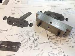
I continued with the work on the Base and completed it over 2 sessions of about 2 hours each.  I took it very slowly when milling the other slot with a 10mm slot drill due to the vibration and loud noise.  The feel on the handwheel while feeding didn't feel smooth at all.  This may be caused by the ER16 spindle chuck I'm using which extended the tool out quite a bit.  I didn't have that problem when using the Sherline's endmill holder but the largest holder I've from Sherline is 3/8"...  Some rectification was done to the Slide's slot as one side is tapered.  The 2 components now fit nicely together and the sliding one against the other is smooth.  4 more parts to complete before I can call this done.
Picture
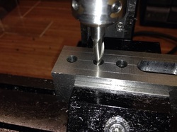
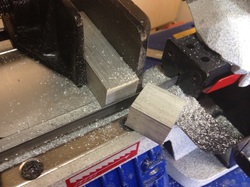
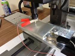
Moving over to the start. The more I use the mill, the more confident I get in getting to the spot I want using the handwheels. The right limit of the slot was set with the tool maker's clamp on the right of the job against the saddle.

Picture
Moving to the left limit and setting the clamp.

Picture
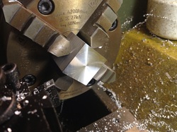
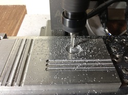
Milling the 1/4" slot with the Sherline 1/4" slot drill. The Sherline's endmill holder in use here.
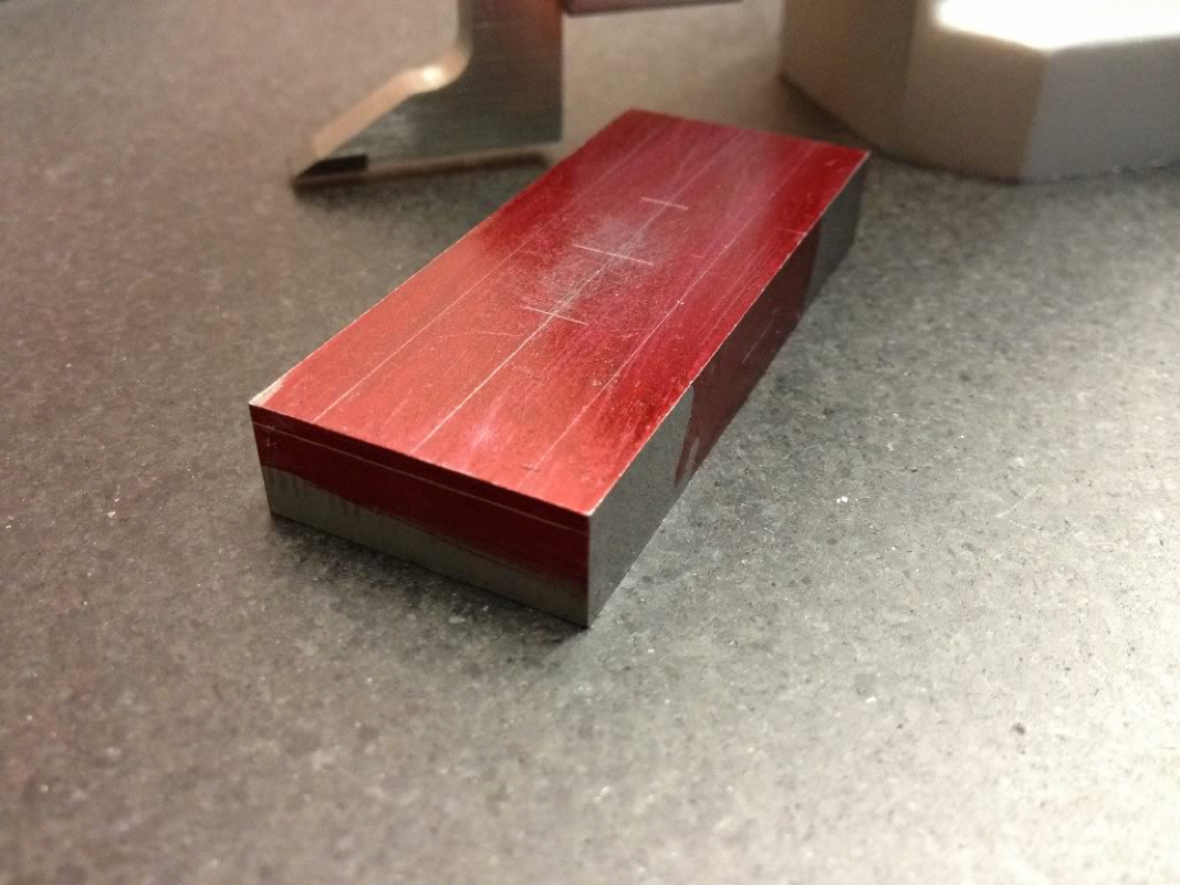
Picture
Slot done.

Picture
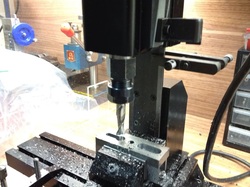
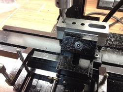
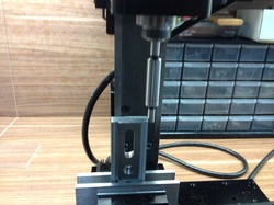
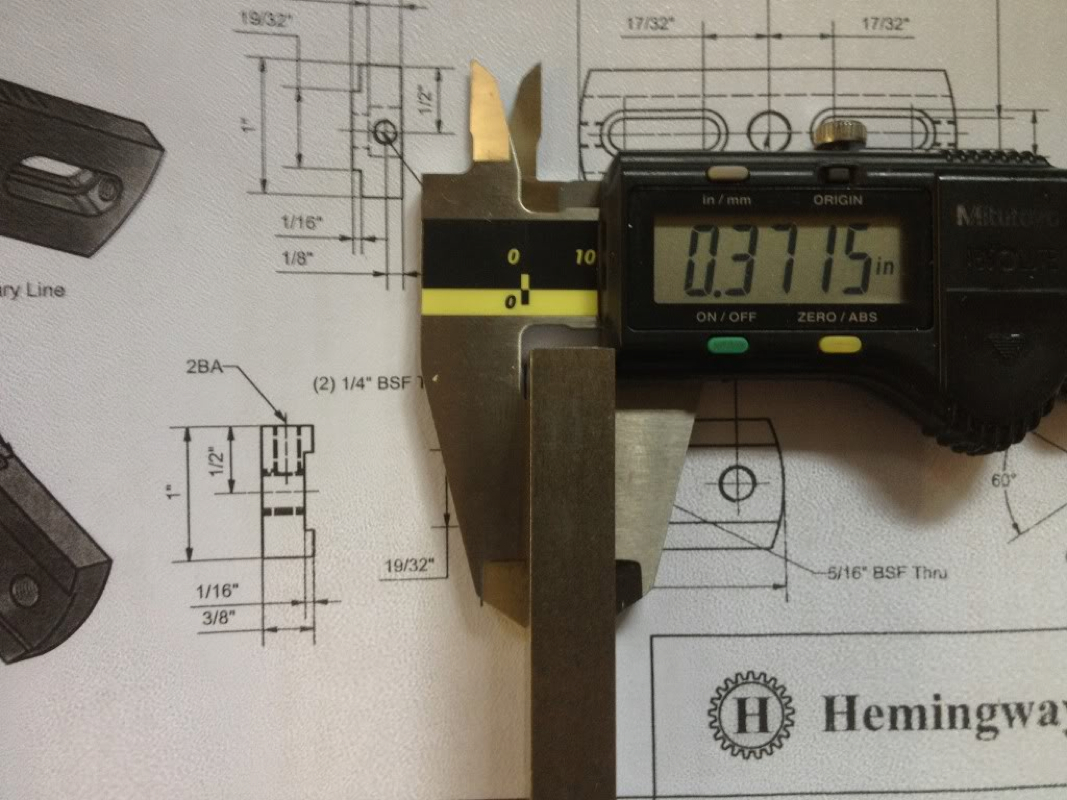
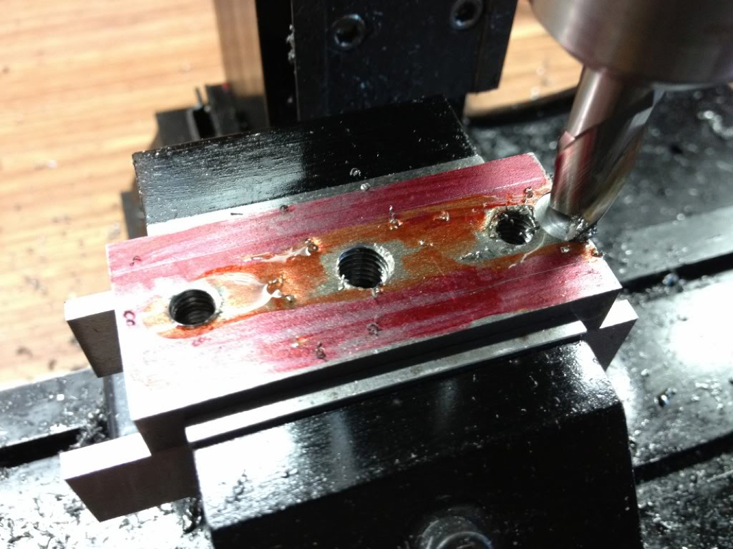
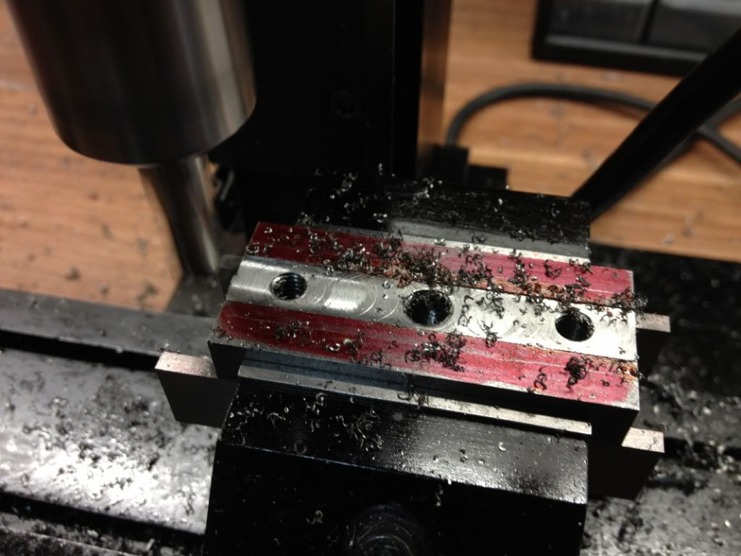
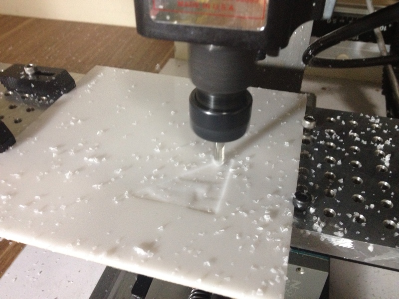
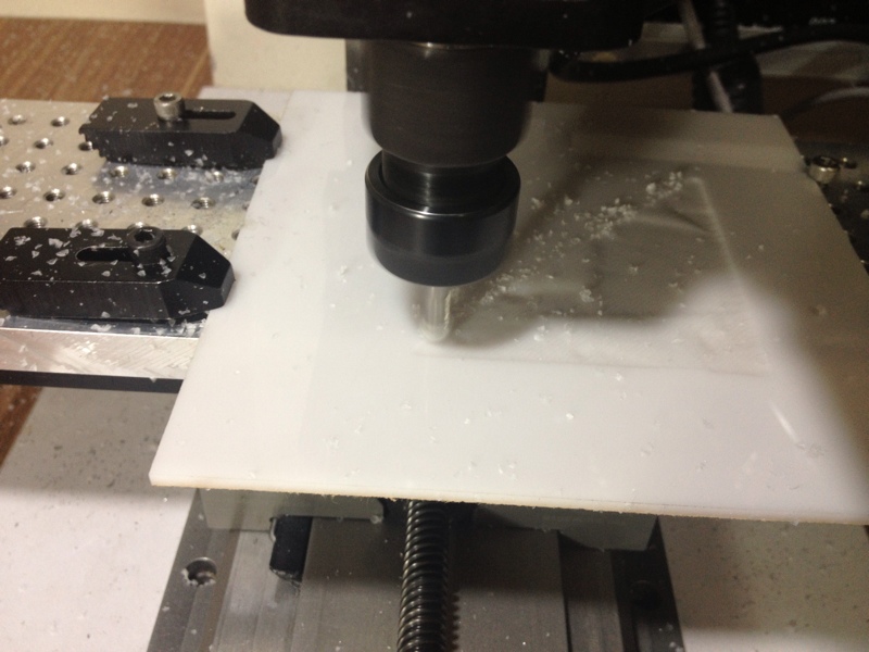
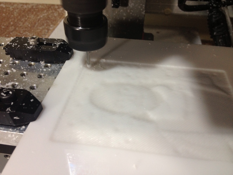
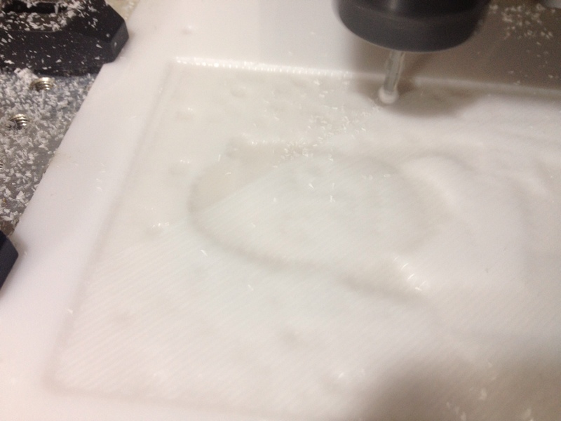
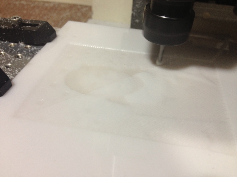
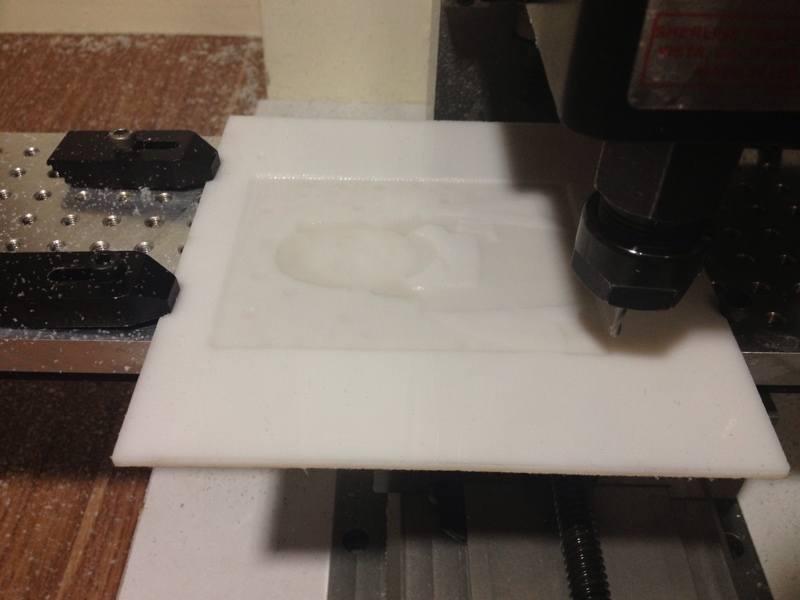
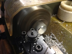
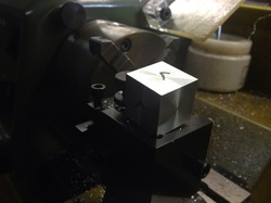
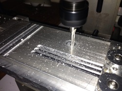
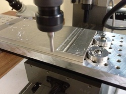
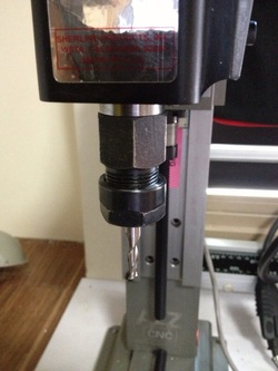
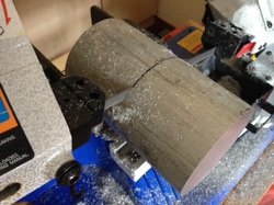
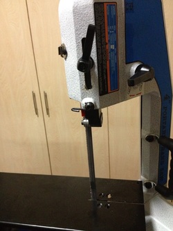
The 10mm slot drill in the ER16 collet chuck was employed to cut the counterbore slot. To set the depth, I plunge the slot drill to the depth of 1/4" and fit another piece of the toolmaker's clamp on the column bed.

Picture
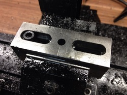
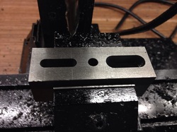
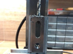
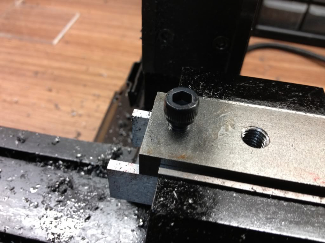
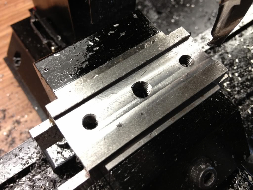
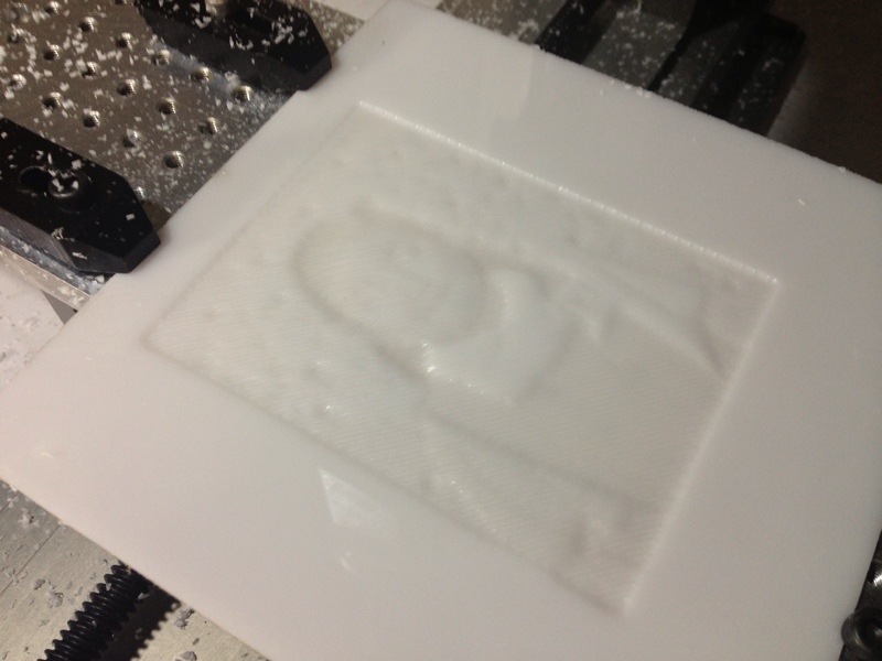
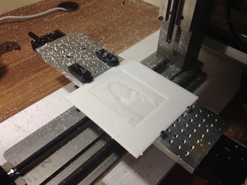
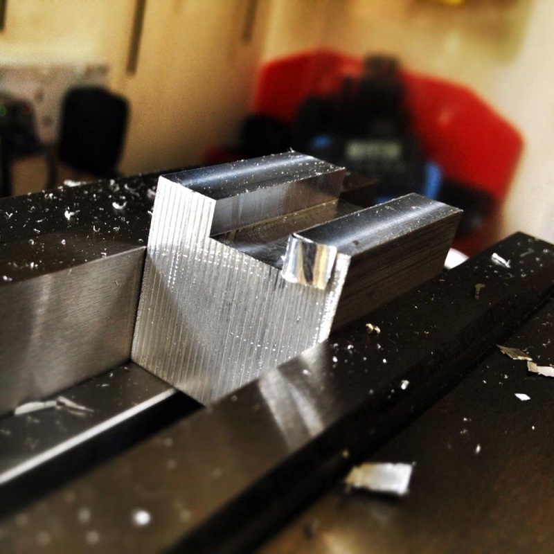
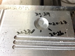
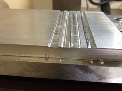
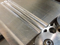
Slot done. I went at 0.25mm per pass to minimise vibration. The cap screw sit flush with the top surface of the Base.

Picture
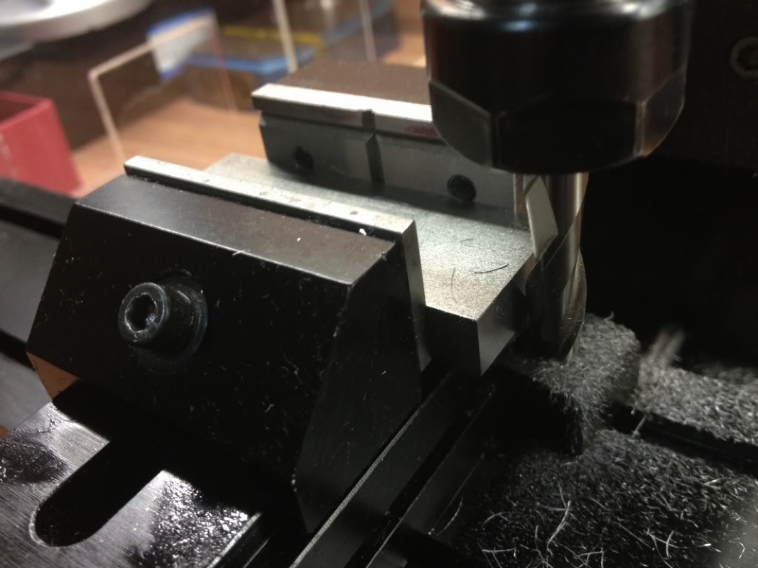
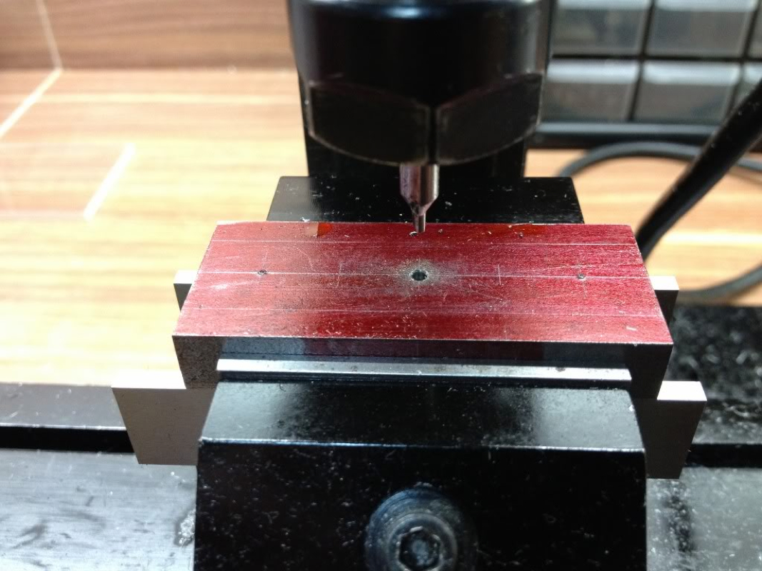
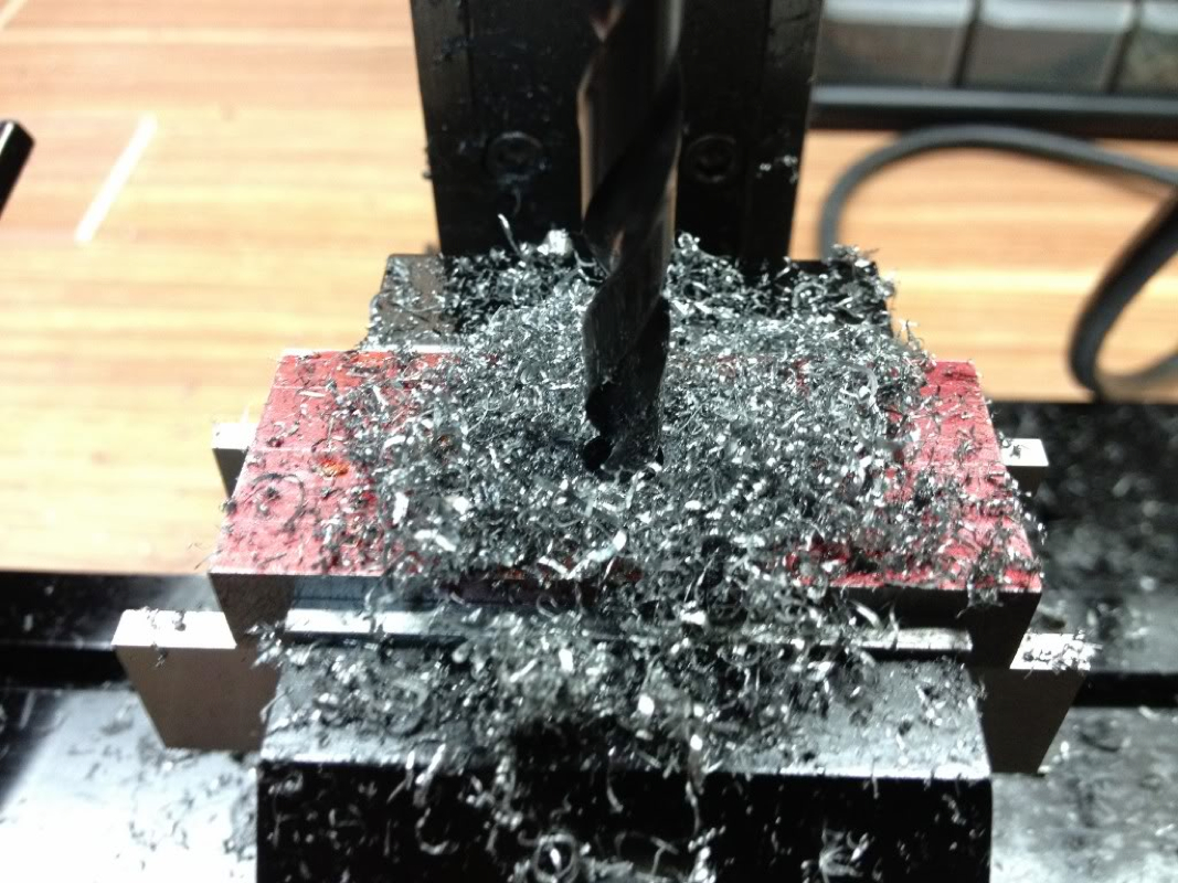
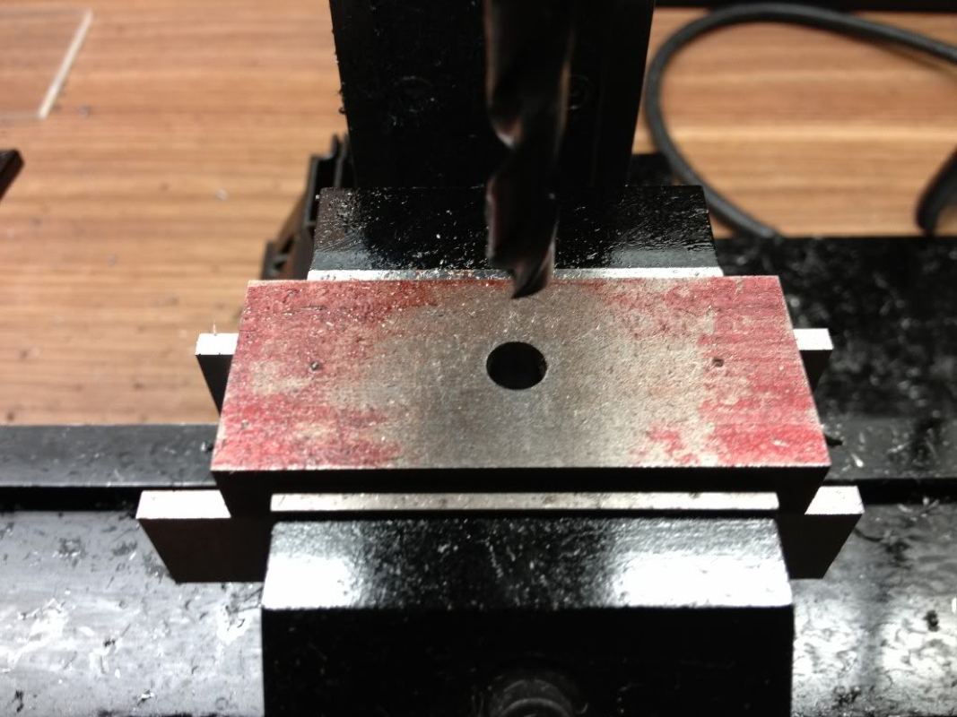
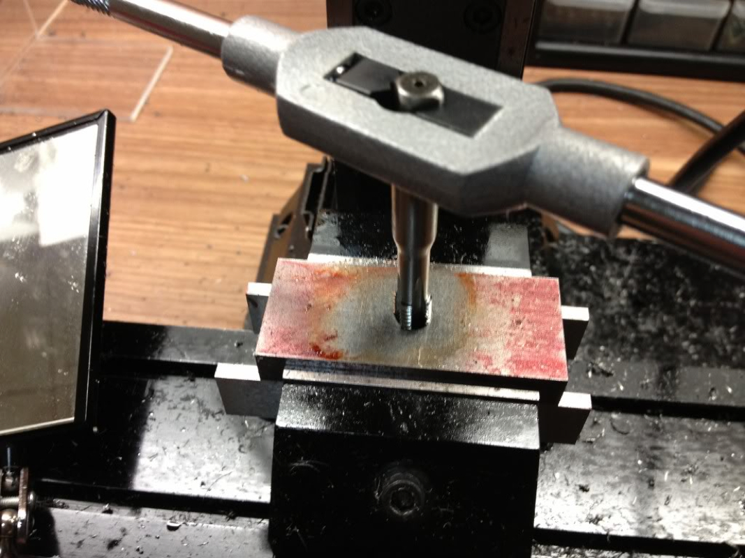
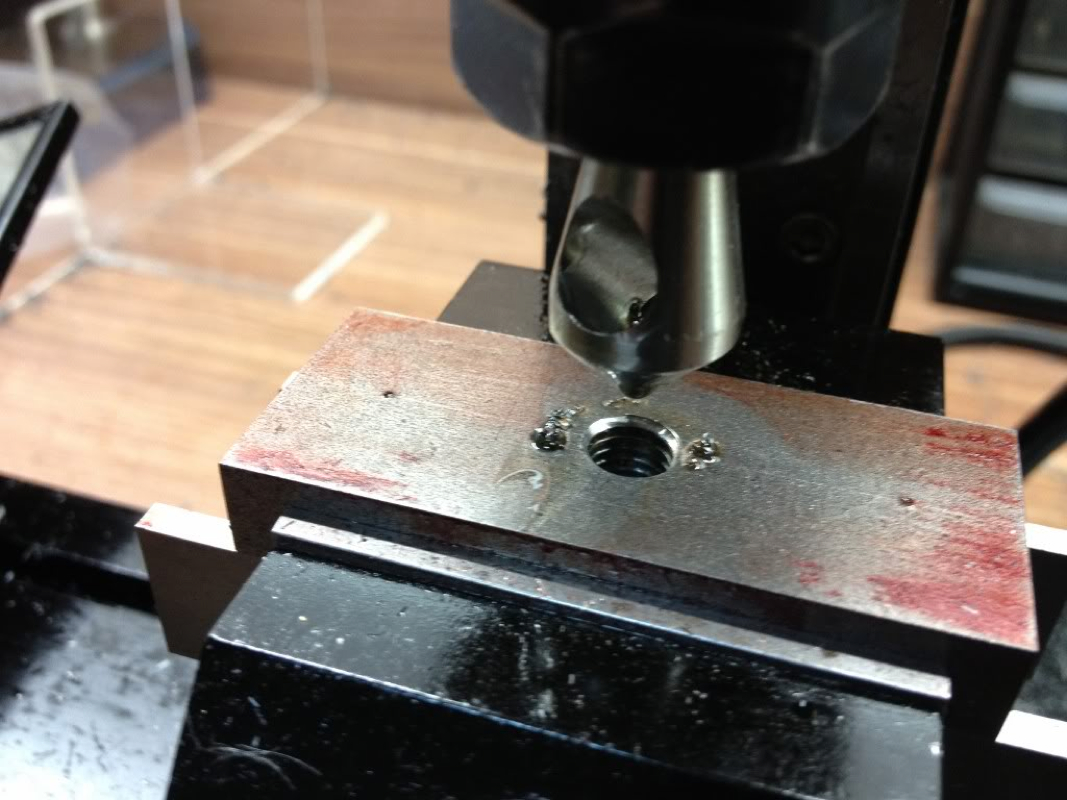
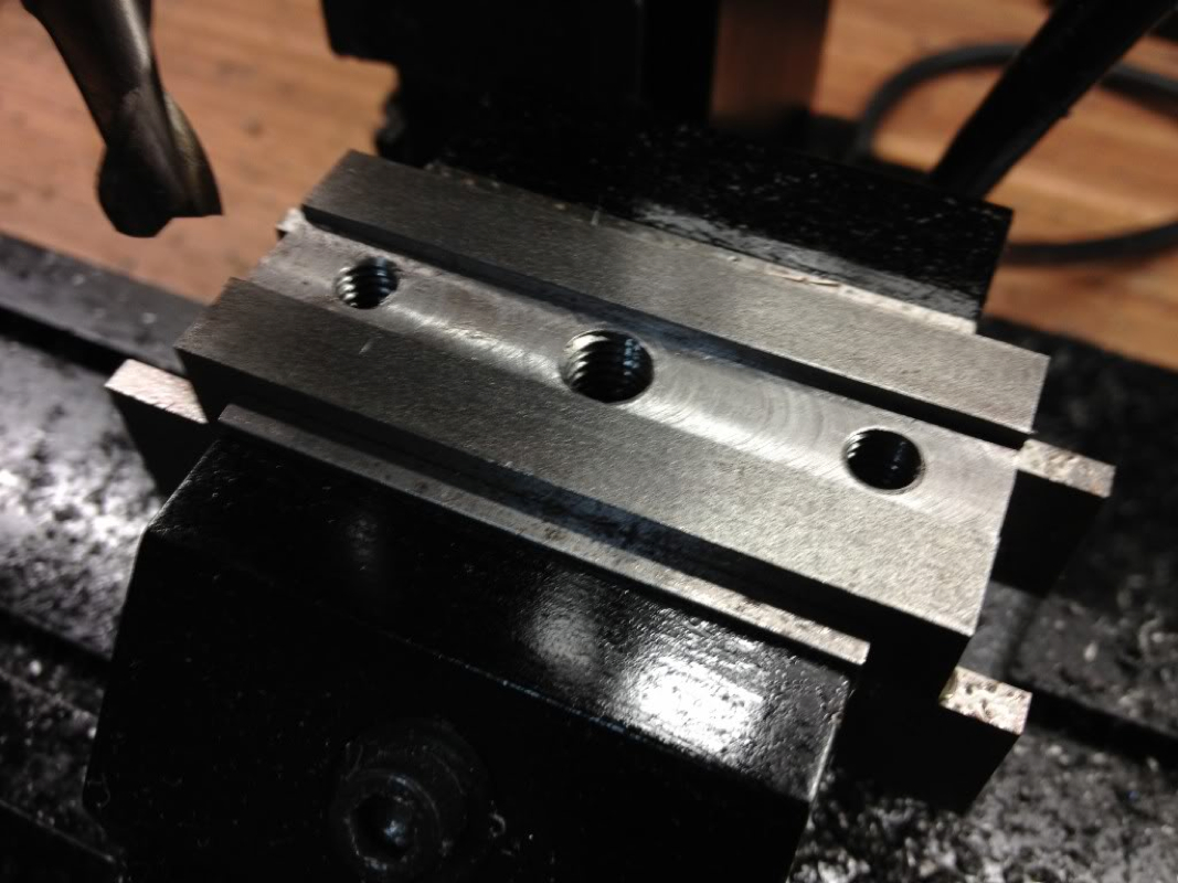
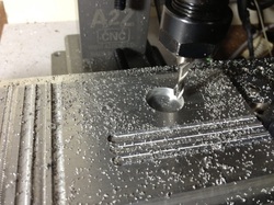
The centre hole enlarged to 6.4mm to tap 5/16" BSF.

Picture
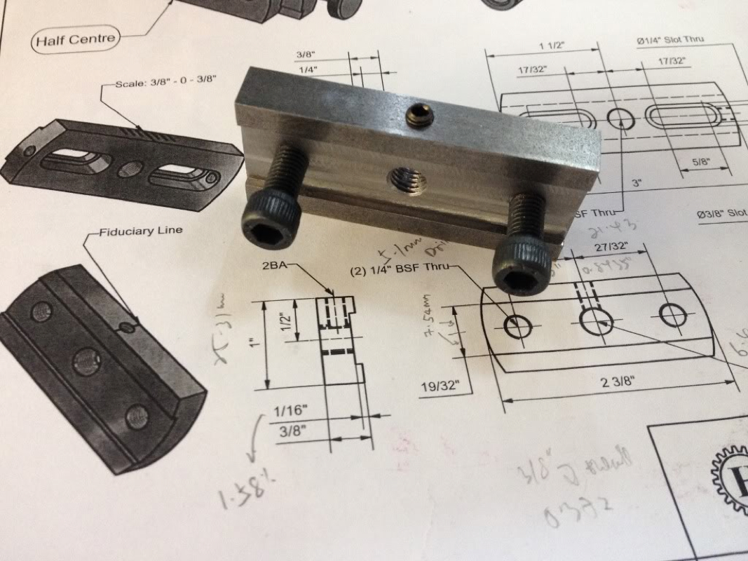
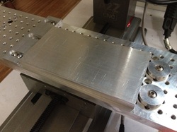
Testing fit. No side wobbling encountered. I'm pretty pleased :)

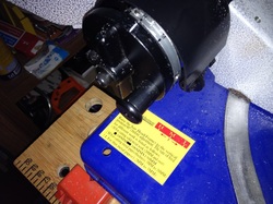
The instruction calls for the 2 x 2BA holes to be done on the drill press.  I was running out of time to set up the drill press (its under the bench...) and so stand the part in the vise and carry on.
Picture
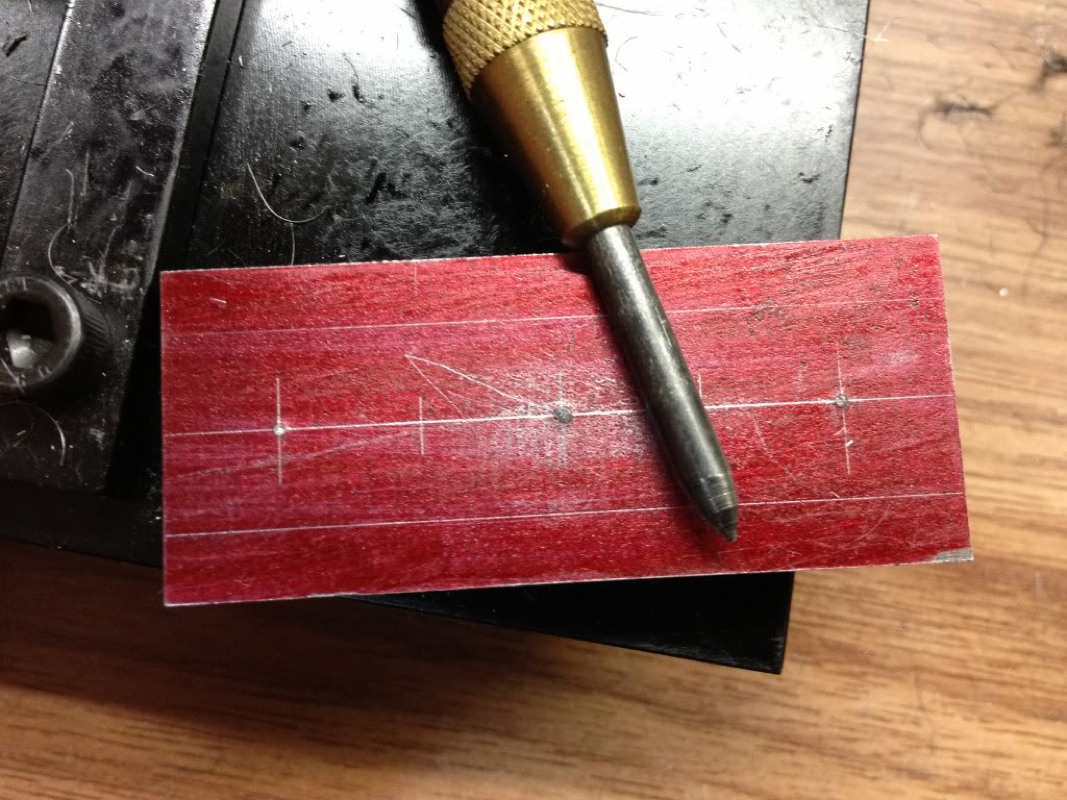
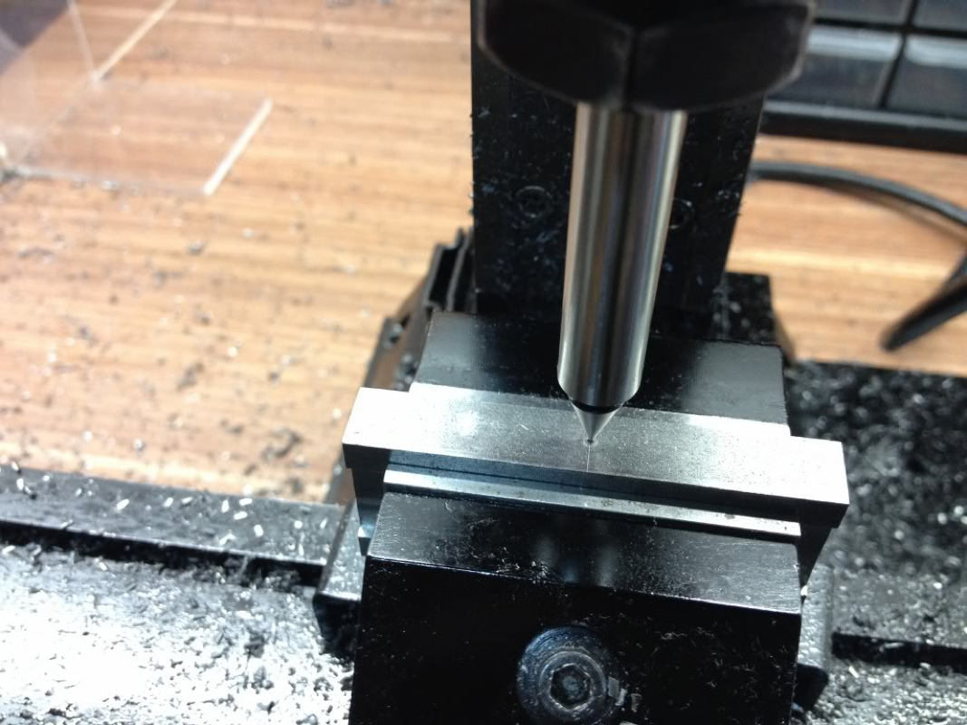
Locating the side and dialed to the centre of the workpiece.

Picture
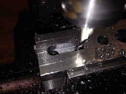
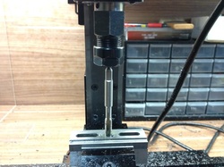
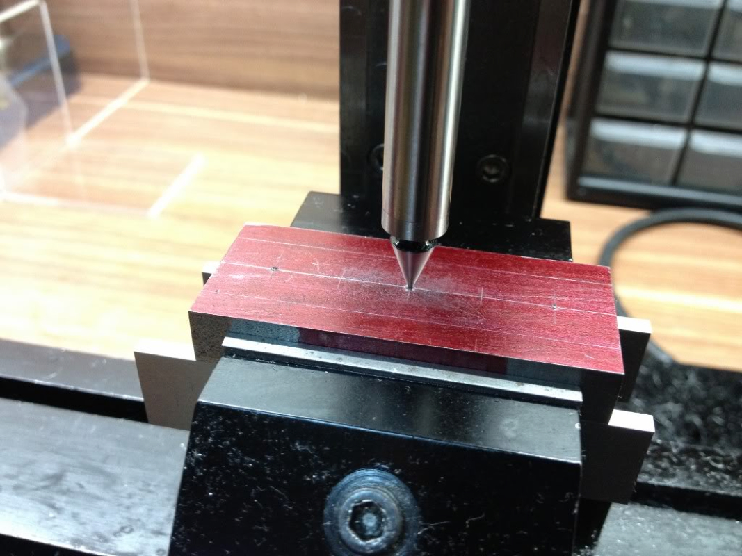
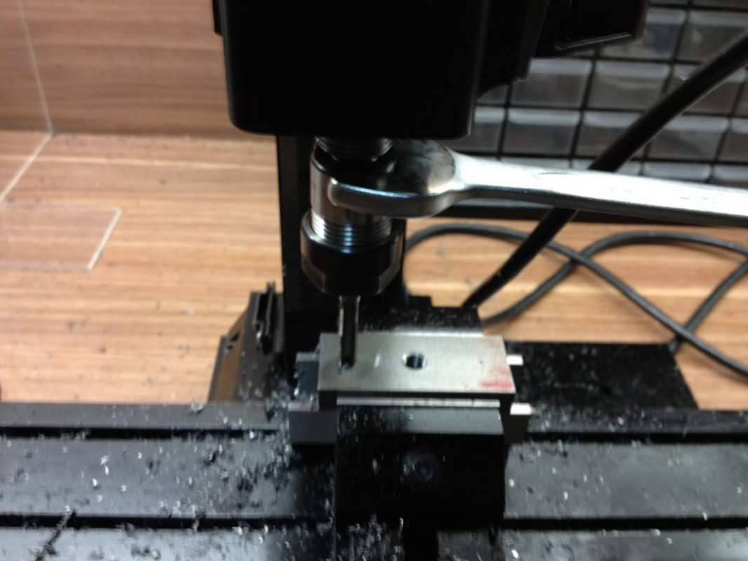
Centre drill and drill through with a 4mm. I'm at the limit of the z travel...

Picture
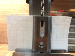
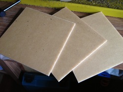
A piece of card stock used at the back to check if I'm right in the middle. Not too bad..

The part was then flipped over to drill and tap the other 2BA hole on the other side.  This completes the work on the Base.
Picture
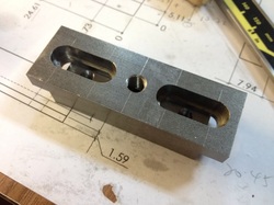
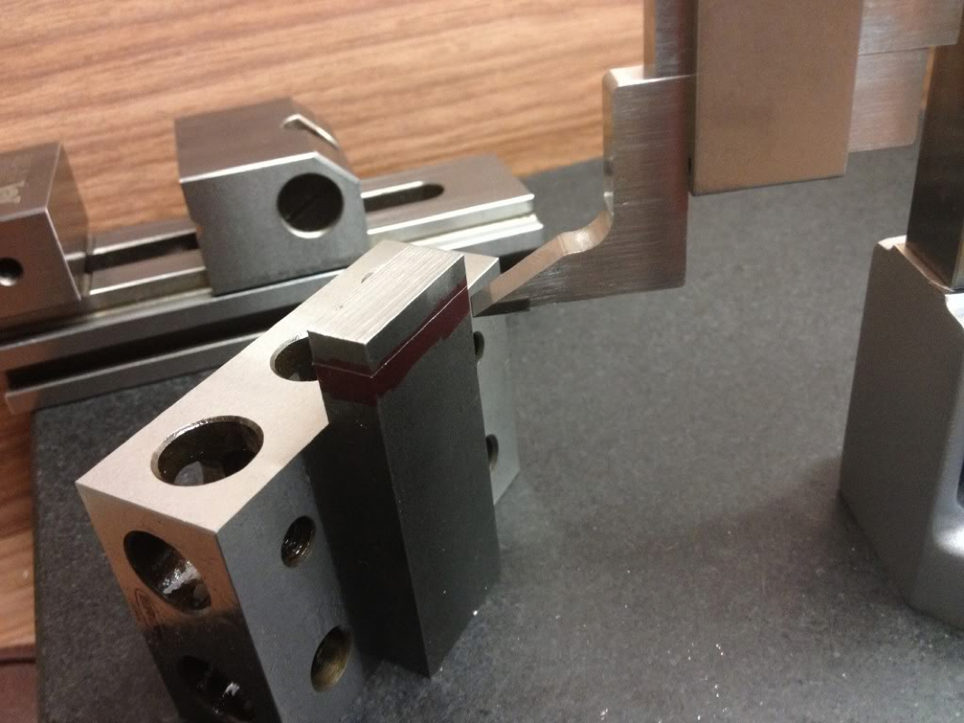
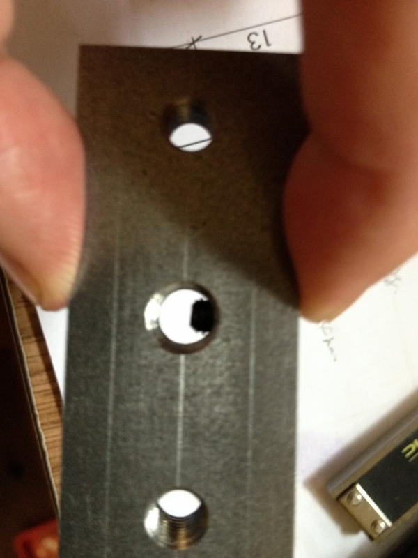
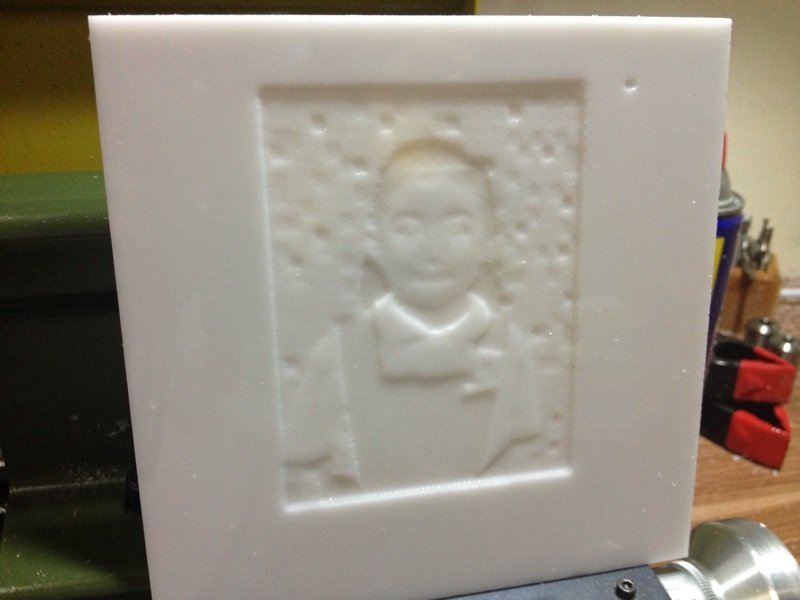
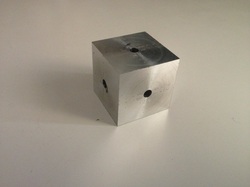
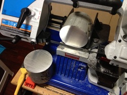
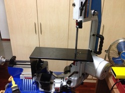
View from the back where the 2MT Arbor will be screwed in from.

Picture
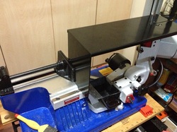
The front. I'm wondering if the screws are a little too long. The drawing shows them as almost flushed with the surface. Can those who did this confirm if I need to shorten the screws?

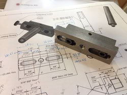
The rest of the work will be mostly done in the lathe.  From the plan, I'm left with making the 2 adjustment screws, the Centre, and the 2MT Arbor.

I'm hoping to get back to the shop real soon!

Blessings to ALL!!!
0 Comments

Hemingway's Set-Over Centre: The Base

29/10/2012

2 Comments

 
The Set-Over Centre is the 2nd kit I bought from Hemingway Kit. The first was the knurling tool which I've not the confident to start working on. Maybe after a few simpler projects I'll start my attempt.

Like most of the little projects I did, I've the drawings drawn on my notebook as 3D models so that I can visualise how things fit together. The raw materials were cleaned up and cut to size to prepare for marking.

Enough of writing. Time for pics...
Picture
I measure the thickness of the steel stock and realised that it is not the 3/8" as shown in the drawing. Same goes for the width, which is narrower than the 1" dimension given in the drawing. I supposed these are not critical.
Picture
Cleaning one side of the stock to use as reference.
Picture
Marking out the other end to mill stock to length. This was the maiden "scribe" by my brand new Mitutoyo Height Gage.
Picture
I can't be more than happy with what I see on the caliper. This is important to me as I've not been able to "hit the mark" on the mill since I started the hobby. Hoping to see more accurate work!
Picture
Marking out the holes and the area to be milled. I used the permanent marker as "layout fluid". Tried shipping in Dykem but my order was held in US and can't be shipped.
Picture
Need to improve on using the punch. Would the optical punch help? Tried correcting by "moving" the punch marks as shown in some YouTube vids - not much of an improvement.
Picture
I was wondering if I should use the edge to move to the centre mark but decided to try using the Mitutoyo Centre Finder. Not really sure of how to use it though. With the point in the punch mark, I adjusted the handwheels on both the horizontal axes till I feel the Centre Finder smooth at the moving part. Anyone can share how this is to be used?
Picture
Centre drill...
Picture
Drilling with 6.4mm drill for 5/16" BSF. Took quite a while to drill through. There was quite some vibration felt during the process, prompting me to reduce spindle speed and ease the feed.
Picture
Hole done. Not very round isn't it...
Picture
Tapping the hole. The spindle with a dead centre was used to start the thread.
Picture
Countersink used to deburr the threaded hole. Should I be doing this before tapping?After finishing with the centre hole, I moved along X axis on both side of it for the 2 1/4" BSF tap holes. The 1/4" BSF tap doesn't have a hole at the end of its shank. So it went into the ER16 collet held in the spindle as guide.
Picture
The Z axis was lowered while the tap was turned using a wrench on the collet chuck.
Picture
Thread done and tested with a 1/4" BSF cap screw that came with the kit. I don't have anything BSF at home to test the 5/16" BSF though. It is meant for the threaded end of the half centre.
Picture
The surface was then cleaned of chips and oil. I redid the layout of the recessed area as the dye of the marker was washed away by the cutting oil.
Picture
I was a little nervous when milling the recess. My last work in steel making the flycutter was quite a painful one; the Sherline mill vibrated like no tomorrow and it was really loud!
Picture
It wasn't that bad this round. Each pass was only 0.2mm deep. After reaching the final depth of the recess (1/16"), the slot mill was moved to open up the slot above and below the centre line at full depth but with rather slow feed and speed. Conventional milling was used.
Picture
The recess completed. I measured the slots and found that I've one end at 15mm while the other end is at the correct width of 15.08mm. Is my horizontal axes not perpendicular to each other? Also, I went 0.07mm to deep though I dialed in the correct amount. I'll do the adjustments when making the Base.
Picture
The top was drilled and tapped for 2BA setscrew, right to the 5/16" thread hole.
Picture
The setscrew installed. You can see that it is not exactly at the centre of the 5/16" thread hole. Don't think this will cause problem.
Picture
The Slide is now completed. I may not want to mill the radius at the 2 ends of both the Slide and Base to simplify the build. Maye I should, to learn how this should be done.
I'll work on the Base in my next session in the shop. One question which I would like to ask. The 2MT arbor needs to be machined and thread 5/16" BSF. I'm scratching my head thinking through how I should be holding the arbor. The Proxxon lathe has a 3MT in the spindle. My Sherline lathe has 1MT. Do I hold it between centre?
2 Comments

Lithophane - First Shot

27/10/2012

4 Comments

 
It started with me checking out Graham's mod on installing the precision leadscrew on his Sherline that I ran across his other work in acrylics.  He has a done tremendous work on illuminated acrylic plates with logos and lithophanes.  I was so captivated by his work that I promised myself that I will give them a shot.

To see how a beautifully made lithophane looks like, visit www.ghqp.com.au and select Lithophanes from Photo Gallery.
Ok.  Now onto my version.  I've this favorite photograph of my elder girl, Alicia, taken by her teacher when she was in Primary 1.  I love the pic so much that I want this to be made into a Lithophane.  It didn't turn out much like what was shown on Graham's site but hey, this is my first attempt.  It can only get better with my next right?  I sincerely hope so.

Enough of talking, onto the pics we go...
Picture
The pic was scaled to 75mm x 100mm as I do not want to spend too much time on setting up the workpiece on the mill.

After importing the pic into BobArt, the depth was set to max of 1.5mm leaving the resolution default.   2 sets of Slice Planar were selected, first with a 6mm ballnose and the second, 3mm ballnose.  The 6mm was to take out as much material as possible, leaving the 3mm for the details.

For the 6mm ballnose endmill, the stepover was set as 1mm.  For the finishing, I went with 0.5mm.

On hindsight, I should have go with a stepover value of 0.15mm for the smaller endmill, like what Graham did.  This should bring out more details, though I'm not very sure if that's the problem.  Maybe the picture size is a little too small...  If you have the answer(s) for me, please leave a comment.  Thank you.

Picture
I've 3 pieces of this Opal coloured acrylic, courtesy of Terence.  Thanks buddy!  As I reached home rather late this evening, I didn't want to spend too much time  thinking of how I should setup the work.  From the pic, you can see the lazy man way.  I did probe various spot of the workpiece using fingers; no popping or bending of the workpiece felt.

To zero the Z axis, I use the little 10-20-40 block I bought from Arc Euro Trade as the base for the tool to contact against.  The block measures 10.7mm.

Picture
Some details showing.

Picture
Her face coming through...

Picture
First pass done.  Though there were ridges everywhere, I kinda like the effect...

Picture
More obvious looking from a distance.  Look at the "snow" next to the mill!  Messy...

Picture
Work continued after tool change.  I almost screw up here.  I forgot to touch off  after tool change and hit the stop button instead of feed hold!  After touching off, I tried resuming the job by clicking on Cycle Start.  The spindle plunge straight down into the work!  Thank God it was at the waste area that will be cut off later.

After bringing the spindle back to zero on all axes, I kept my fingers crossed while hitting the Run From Here button.  Though reading so much of complain on this function, I encounter no problem with it.

Picture
More details showing with the 3mm ballnose endmill.

Picture
Starting to take shape.

Picture
Just look at how close I am to the end of Z axis.  I'll have to work out a jig if this is going to be something I want to do for longer term.

Picture
End of cut.  The details on her face didn't come through very well.  The mozzaic wall that I intentionally kept in the pic wasn't presented nicely too.  Sigh... Need more information on how to do a proper Litho.  Anyone can lend me a helping hand?

With my first Litho done, I tried placing it against light source to see if I can have it miraculously appear as those I saw on Graham's website.  Said to say nothing close...  Being known to have thick skin, I'll still show them here for your comments or criticism.
Picture
Light from front. You can see the little hole on the right. That is from the silly mistake I made during tool change.
Picture
White light from the back. Eeeewwww.....
Picture
From top front using the bedside lamp.
Picture
Medium intensity from the bedside lamp.
Picture
Low setting from the bedside lamp.
Picture
Can't recall what I tried. But it seemed to be the best so far.
From the use of different light source and intensity, I found that the brighter the light source, the more obvious the mistake(s) made on the Litho.

To bring out more details and get rid of the cut lines, I'll be experimenting with different depth, sizes of ballnose end mill, and stepovers.  If there is anyone reading this with experience in making Litho, I would love to hear from you.  You'll likely help me "stepover" all the pain in testing with different settings.  This piece took me almost 2 hours to complete.  This is excluding time taken in generating the toolpaths, setting up etc.

The Sherline spindle runs at max of 2800 rpm.  If this is too slow, I've the 10k pulley set that I can install.  Also, I've the Proxxon IB/E spindle that I can put on the mill for up to 30k rpm cut, but that will have to wait till I fabricate the mount to adapt it to the mill.

Ok, hitting midnight soon.  I've to get up early tomorrow to prepare for church.  Till the next session, be blessed!
4 Comments

Turner's Cube - Part 1

26/10/2012

6 Comments

 
It was a fun morning in the shop today with Terence coming by to do some work together.  We have been discussing on doing some projects together and wanted to start with the Touch Probe for the CNC mill he drawn up.  As he has no experience in turning (not after leaving Secondary School many many years ago), we settled for the Turner's Cube as the starting project.

This is how a completed Turner's Cube looks like, taken from Bob Warfield's CNC Cookbook:
Picture
Click on the pic to go to CNC Cookbook. Bob has many interesting articles on machining and is the author of GWizard Calculator - a really helpful tool to have even for home machining.
It is a simple beginning project, I read online, for most people.  There are many videos and pictures on the net showing different versions being made, not just on the lathe, but also on the mill.  This project will be a good one for Terence to gain some hands on with the lathe and for me to learn the entire process from planning to completion and to build up the required confidence.

We started with a square bar of 1" aluminium I've in the box.  To keep things simple, a smaller cube was agreed upon.  Some time was spent facing the sides to bring the cube down to 24.5mm.  Keying that in the GWizard Turner's Cube calculator, the other dimensions were given.

We didn't get to finish the project in one session as I ran out of shop time (meeting my parents to visit my grandmother).  Hope to finish it up in our next session.

Not many pics this session.  We were chatting away while I show the big guy some basic lathe work, which is all that I know... We hope to learn together, motivating and teaching each other up the learning curve of machining.
Picture
The 1" square aluminium bar stock of unknown grade being cut in the bandsaw.  It was a quick cut with feed set at 'M'.

Picture
The workpiece was then cleaned up in the lathe using the automatic 4 jaw chuck.  I really love this Rohm chuck - very good in precision despite being a scroll chuck.

Picture
Couple of sides done.

Picture
All sides done and ready for the next stage.

Picture
The first drill called for in the GWizard Calculator is a 3.5mm drill.  Terence suggested drilling each side till half the depth so that if the cube is not in alignment with the centre line during chucking, we'll still have the holes in the middle of each face.  It is a very good idea and makes lots of sense!  I would have drill all the way through on 3 sides to save time.  But the result proved the added step to be unnecessary as all the halves lines up very nicely with each other!  I was surprise with the result, adding to my confident with the lathe and the Rohm chuck.

This was where we stopped.  A total of slightly less than 4 hours was spent in the shop, including chit chatting, introducing the lathe and parts, deciding if the mill or the lathe should be used for the ops, and the actual work. 

Before Terence left, I took the opportunity to show off how deep the Wabeco F1200 can cut in aluminium in one pass.  But being a "chicken", I dialed in only slightly more than 4mm depth and did the cut with a 10mm HSS endmill.  Some chatter was felt (and heard) when I was feeding slowing (chicken enough?).  As I increase the feed with the handwheel, I realised that the mill can in fact be used more aggressively given its rigidity.  I read from Wabeco's instruction manual that it can take, without any problem, cuts up to 10mm deep in steel with a 10mm endmill.  Wow....  But I wonder if that is possible with my MT2 spindle bore.  On hindsight, I should have pay for the ISO30 tool holding option, which is another EUR 158.82...
Picture

A video of the cut, taken by Terence.
6 Comments

Laksa For Lunch

24/10/2012

0 Comments

 
Many tense moments in the office that I decided to have lunch and have it out of office. While waiting for a cab, I Whatsapp Terence to see if he was available to have quick lunch together. He obliged.

After having a quick lunch, we pop by a shop nearby to take a look at the Taiwanese bandsaw I saw some months' back. Instead of that big, ugly but cheap bandsaw, we were shown a exact replica of the WayTrain I bought from Hup Hong. The similarities are right down to the font used on the labels! The only different I can see is the absence of the WayTrain logo... all these at about SGD200 cheaper than the price I paid! Not to mention the free delivery... I'll get some pics from Terence to put up in my next post.

I bought myself these:
Picture
Nice? This set is for use with my Makita power driver. Just want to buy something... Sigh...

One thing I realized; when 2 guys met for lunch and a little shopping, we can do everything within an hour... Lolz... This includes the time chit chatting about mods and stuff.
0 Comments

Glitch in posting comment

22/10/2012

0 Comments

 
I want to thank Javi from Spain for bringing this to my attention.

It started with me receiving 5 emails notifications for a single comment posted by GeneK. Seeing all 5 were for the same post, I approved 1 and deleted the rest. I thought this as a one-off.

When Javi posted, he received a message saying that this comment has not been successfully posted. At my end, I received, again, 5 emails notifying me of the same comment requesting for approval. Javi dropped me a note via the feedback form to let me know about this. This is a strange behavior that I've not encountered before.

I've sent a note to Weebly support. Hope that they'll respond soon and fix this up.

Meanwhile, do keep your comments coming. They provide me with the motivation to do and post more.
0 Comments

A2Z Monster Mill: Circular Pocketing

20/10/2012

12 Comments

 
I've to blame Terence again (seemed like he is so nice to pin all the blames on...).  He mentioned that his mill couldn't cut a true circular pocket while he was working on the turner's cube on his mill.  His remark reminds me of the video posted by Hossmachine.  He was testing the backlash compensation settings on Mach3 by milling circular pockets.  This stirred me to do the same test as the backlash comp in my Mach3 setting was just done a couple of weeks back.
Picture
The test was done on the same piece of aluminium stock used in the afternoon to test DOC.  The Circular Pocketing Wizard in Mach3 was used to generate the GCode for a 20mm diameter circular pocket.  As the test was to see how round will be the circle, I set the DOC each pass conservatively at 0.25mm.

Picture
Mid way through pocketing.  The feedrate I set is painfully slow at 150mm/min.

Picture
Done finally... 

Picture
4 measures  were made.  The closest to the diameter I set: 20.24mm.   Why the 0.24mm from my 20mm diameter?!

My circle is not very round too - I'm out by 0.03mm.

2 things I've to get settled before I start on any projects using this mill:
1) Motor Tuning - to make sure that when I say move 10mm, the table indeed move 10mm (or within a certain range which I'll try to figure out what's good enough).
2) To measure backlash again - Maybe 0.03mm is good enough but let's see how much more I can bring this down.  Again, no target set yet.


I've a video taken when the mill was making the 2nd last pass.  I am wonder, if any kind soul out there can help answer, if the sound created by the endmill plunging into the workpiece is a sign of things not done right. 

Do drop me a comment please.
Ok, I'm supposed to get ready the Sherline Lathe so that Terence can pick it up tomorrow night.  I want him to try playing on a lathe before deciding which one to buy.  Problem is, I'm feeling really tired.  I'll try setting it up tomorrow morning if time permits.  Got to reach Alicia's church by 9.30am.

I am tempted to go for the Wabeco D4000 when Terence asked me if I am thinking of letting go of the Proxxon PD400.  This presented an opportunity to go for the lathe I always wanted but settled for my 2nd choice due to budget.  I'll have to give this some thought given the uncertainty in the market.  Also, I've not explored the full potential of the Proxxon.  It will be a waste to swap it out at the moment.   I'm rather divided...
12 Comments

Testing Depth Of Cut on A2Z Monster Mill

19/10/2012

0 Comments

 
I've to blame Terence for this.  I've not been a diligent guy when come to testing things.  We chatted via Whatsapp till late last night and among many things on machining and machines, we spoke about the rigidity of the Monster Mill.

He was sharing that he felt his mill breaking apart when he was mill deeper (can't recall how deep), so much so that his son ran into his shop to see what happened.  I was rather disappointed when I hear this as I had just bought the column and had it installed.  Before I dozed off, I make a mental note to do some testing the next morning.

As I'm quite a "chicken" myself when come to machining, I set the maximum depth of cut (DOC) to be 1mm for the tests.  This was the max I think I will go when using the mill as I'm not in control, so to speak, when codes are being run. 

The stock was setup using the low profile clamps I bought together with the milling plate.  A piece of aluminium I have lying around was used.   DOC to test will include 0.5mm, 0.75mm, and 1mm.
Picture
From the GWizard Calculator, I'm supposed to go at feed of about 200mm/min.  Being a "chicken", I cut it down to 180mm/min to "play safe".  This may be what Bob Warfield said not to do many a times about babying the cut.  Since I'm in "discovery" mode, I'll just use what I'm comfortable with.

Picture
The aluminium plate being setup for the cut.  I hammered it down when tightening the cam screws on the right.

Picture
Touching off to find Z=0 using the Mach Blue function.

Picture
The first slot on the right was a mistake.  I typed G0 instead of G1... Thank God I started at 0.25mm DOC.  Otherwise, I may have a broken endmill.  FYI, my rapid was set at 500mm/min.

The 2nd slot: DOC 0.5mm, F200, 2000 rpm.

Picture
The last 2 slots from right to left:
DOC 0.75mm, F180
DOC 1.00mm, F180

It seems to me at this point that I've the mill trammed along Y and that the mill did its job well with even up to 1mm.

I've no intention to go beyond 1mm.

Picture
Back track a little, I was using the A2Z ER16 to 3/8-16 adapter.

Picture
Spindle speed was adjusted using the Tachometer I bought from eBay.  This is my 2nd piece as the 1st one broke after just a couple of use.

Picture
Now for test cuts along X axis.  DOC 0.5mm, 0.75mm, and 1mm.  Feed of 180mm/min used throughout.

The cut pattern at the cut surface shows that the mill is pretty much in tram along X too.  I'm so happy!


I've taken a video using my iPhone showing the 1mm DOC.  Pardon me for the last part of the video.
That's all I've this Saturday.  If time permits, I'll start the Lithophane of Alicia's Primary One photo later of the day.
0 Comments

Terrence Came Visiting!

14/10/2012

9 Comments

 
Fellow hobbyist Terrence came by my place this late morning. He bought a piece of 4" diameter aluminum stock which he wants it cut into shorter sections. I've just the tool for this!

The little 4" bandsaw I bought took about 1/2 hr to cut through the 4" stock, leaving us little time to cut the 2nd piece. So he left with just 1 cut piece as I was also getting myself ready for my Saturday duty as a driver.
Picture
A huge piece of aluminium stock 4" in diameter.  It took the bandsaw around 1/2 hr to cut through it to make the first piece.

Picture
After Terrence left, I started making the last cut while preparing to leave home.  I've to stop here to resume later.

He brought with him the opal colour acrylic which he helped me to purchase while he was at Dama. This will be the start (I hope) of my venture into Lithophane.
Picture
The Opal colour acrylic.  Each measures 150mm x 150mm x 3mm.

During his visit, Terrence showed me the new Indian made slitting saw holder he bought from Chan Man Lee. The 1/2" shank is too big to fit into the 1/2" hole of the A2Z adapter.

I tried setting up the holder between centre using Proxxon version of the lathe dog. It didn't fit properly. Will have to think of how to use a commonly available type with the Proxxon.

We also wanted to try boring out the adapter but didn't have sufficient time to do a proper setup with a 4-jaw chuck. So he brought it back to try it on his mill with the boring tool.

We are hoping to jointly work on some projects together. May start with Tryally's vise or the touch probe.   Terrence, bring it on!
9 Comments

Bandsawing...

13/10/2012

0 Comments

 
I came back home after dropping off my dearest and visited the client to finish up with the cutting for Terrence.  The cut was completed but I am not impressed with the time taken to cut through the 4" aluminium stock.  I remembered a setting for feedrate in the manual and started investigating if I'm doing something wrong.  Found that the default setting at L is meant for pipes.  According the the sticker at the back of the bandsaw, I'm supposed to set  the feedrate to H for solid metal greater than 20mm thick.  To set the feedrate, the upper section of the saw has to be swivelled upright.

I've have it set now but do not have time to test if this would speed up the cut.  If its not too late when I reach home after church and party (with some family friends for early Halloween party), I'll do some testing.

Some for some pics.
Picture
The completed job.

Picture
The feedrate setting.  If you can zoom in on the pic, the yellow label would specify the type of job for each setting.  This can't be adjusted when the saw is in its horizontal mode.

Picture
Standing the saw upright.  I put on the table that came with the saw  just for fun.  It is now in vertical mode though I've not put on the 2 bolts that hold the table in place.

This is the first time I'm exploring this and like the idea of having a 2 in 1 machine!

Picture
The "leg" of the table secured by the clamp.

Picture
A closer look.  The handle at the top is for adjusting the blad guard.  I adjusted it up for the earlier job.

Looks like that's all for now.  Leaving home in another 10 mins time.
0 Comments
<<Previous

    Enter your email address:

    Delivered by FeedBurner

    Categories

    All
    3d Printer
    Er32 Collet Chuck Proxxon
    Misc
    Misc Projects
    Projects
    Proxxon Pd400
    Sherline / A2Z Monster Mill
    Things I Bought
    Wabeco Mill

    Archives

    June 2018
    January 2017
    December 2016
    August 2015
    July 2015
    June 2014
    May 2014
    December 2013
    November 2013
    October 2013
    June 2013
    March 2013
    February 2013
    November 2012
    October 2012
    September 2012
    August 2012
    July 2012
    June 2012
    May 2012

    RSS Feed

Powered by Create your own unique website with customizable templates.