Wongster's Production
Share it on
  • Home
  • Blog
  • My Old Blog
  • My Shop
  • Resources
  • About Me...
  • Contact Wongster

The Tachometer

31/12/2016

0 Comments

 
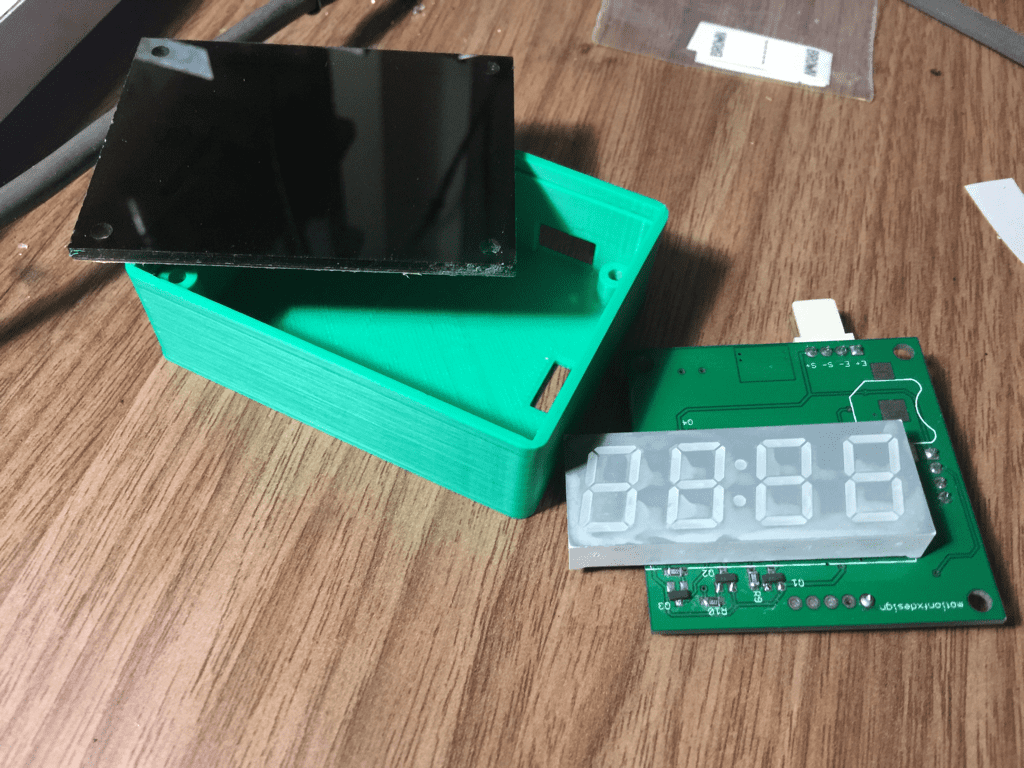
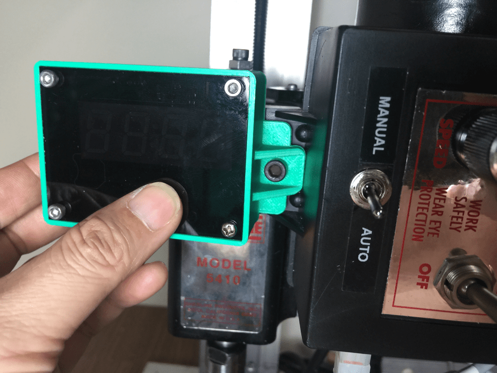
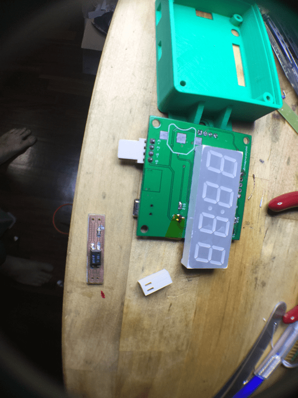
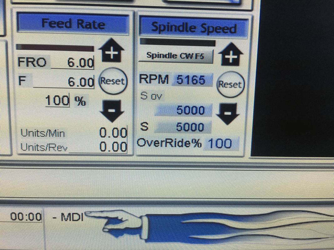
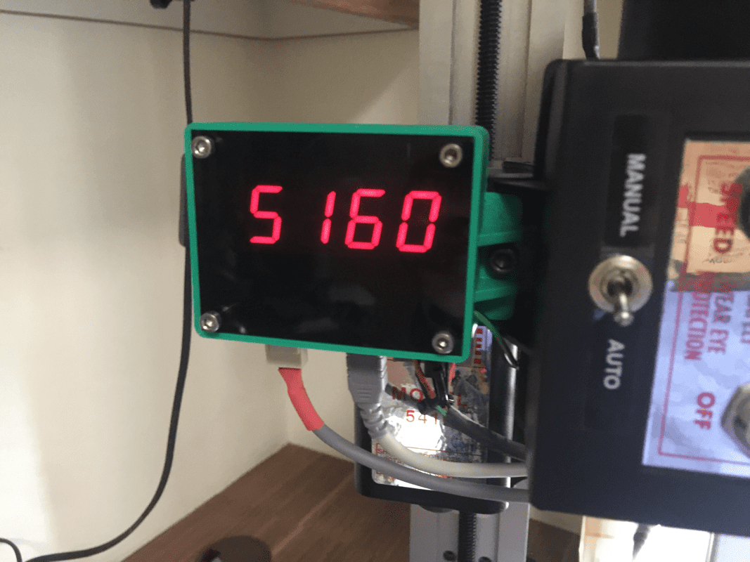
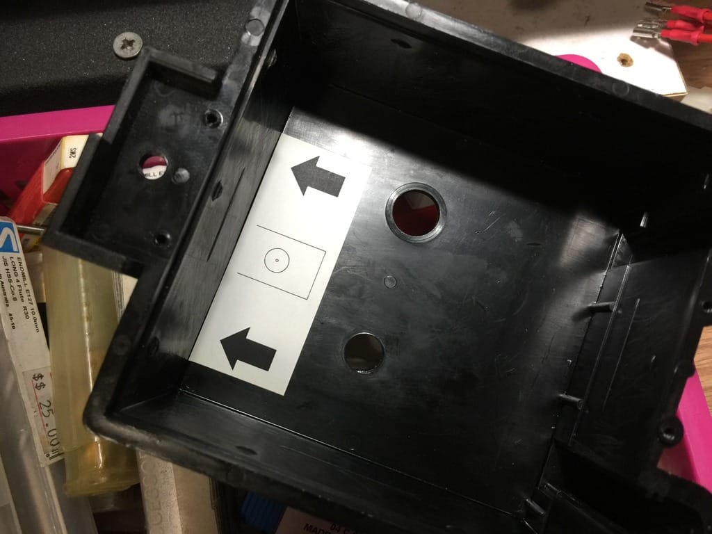
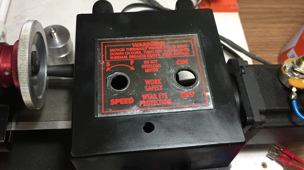
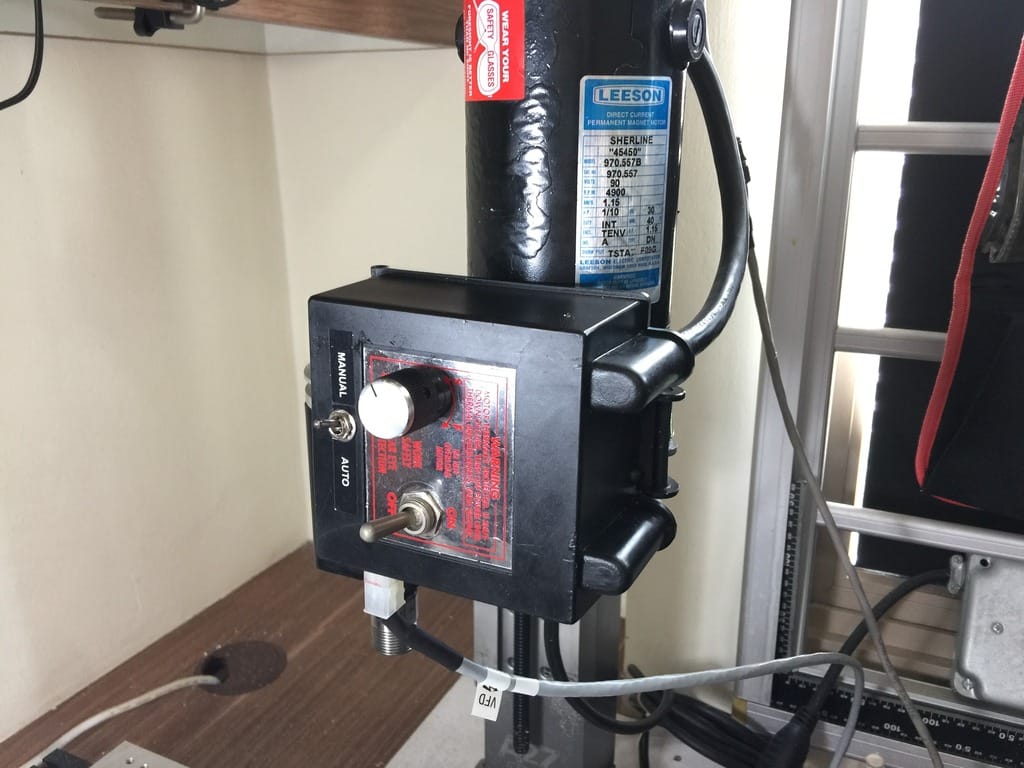
With the wiring of the KBIC out of the way, the next is to either buy or make a tachometer to display the spindle speed and also to feed Mach 3 the pulses coming out of it.  Before i know it, Terence has already completed one and generously shared it with me, all parts included.  The completed tachometer uses 7-segment LED as display.  From the case he printed, it looks good through the tinted acrylic front cover.
Picture
Picture
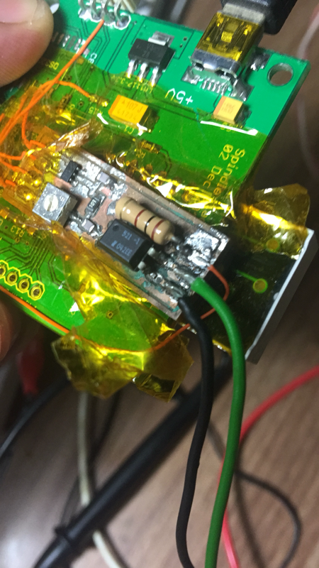
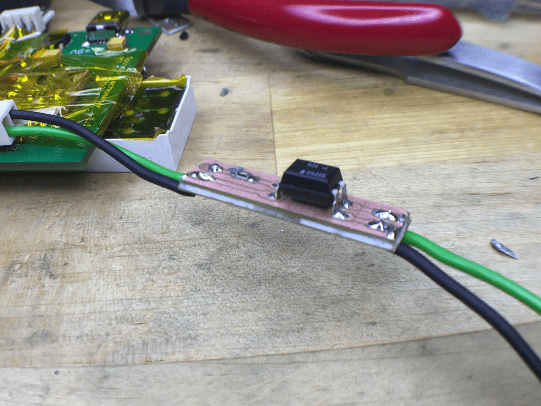
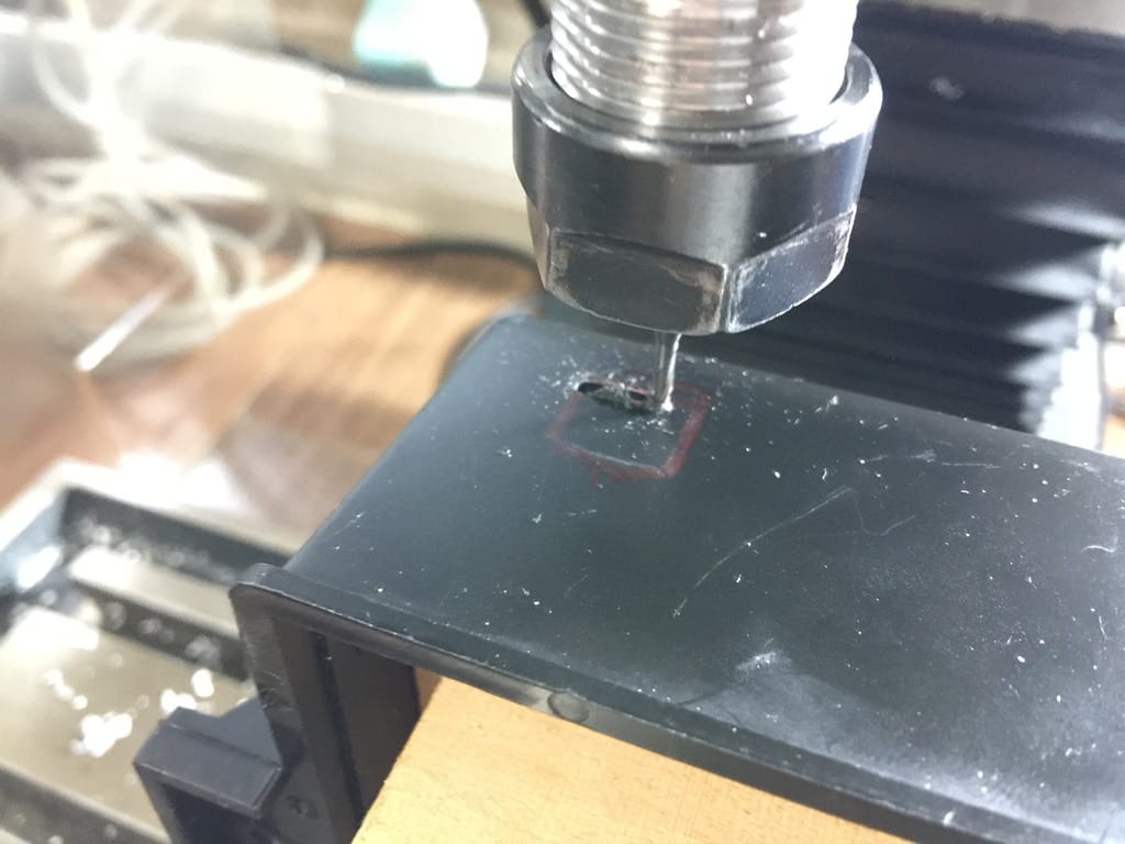
Next is to wired it up so that it can signal to Mach 3 via its index pin. This, I encountered lots of problem because of electrical noise in my system.  To solve this problem, Terence designed an addon board to filter out the noise so that the microcontroller is able to see the pulses without false trigger.  With the addon board design done, I asked for the files to experience milling a simple PCB on my own.

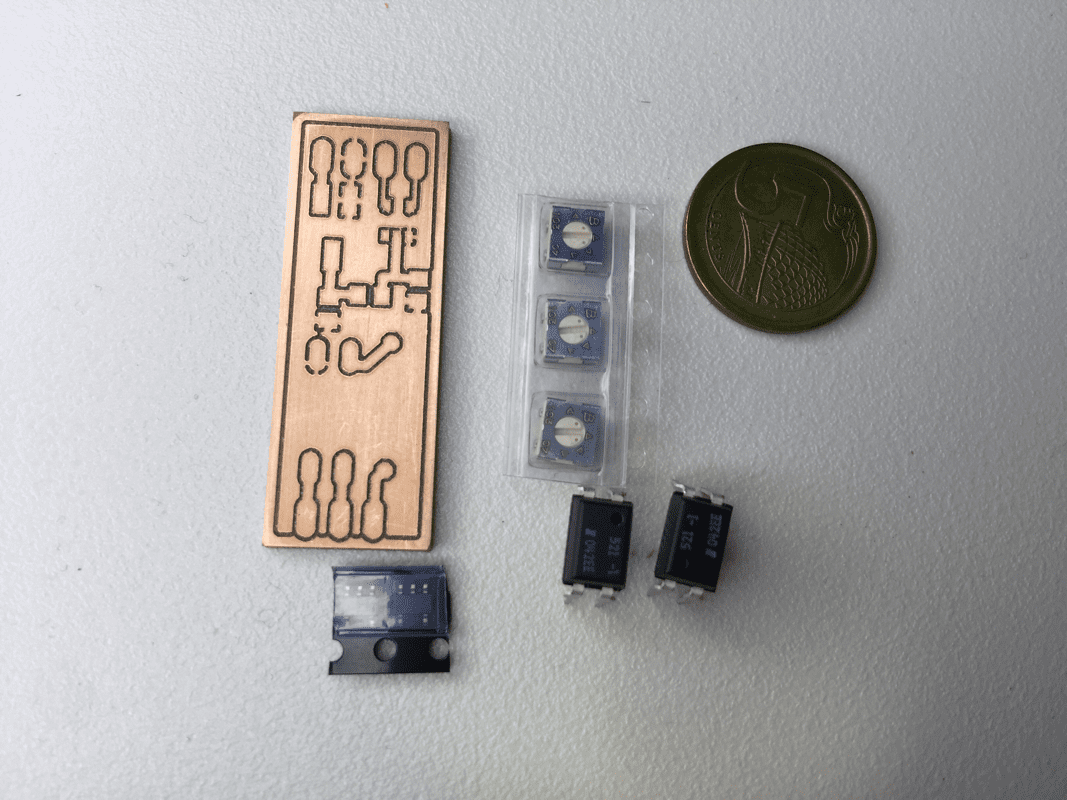
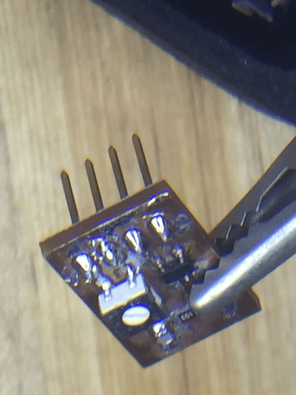
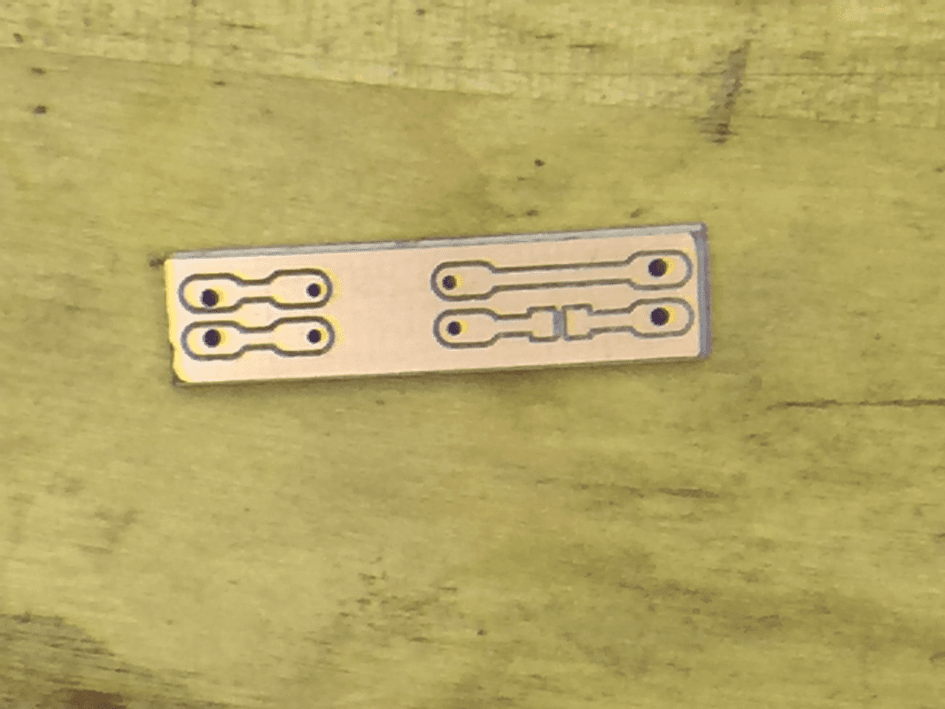
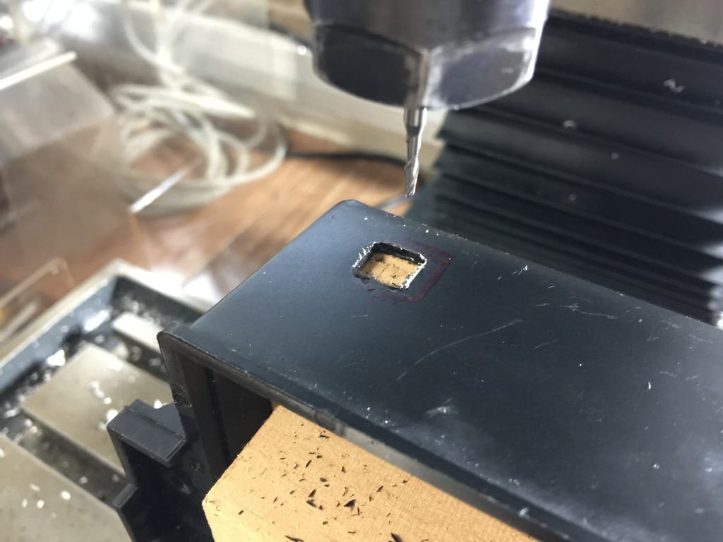
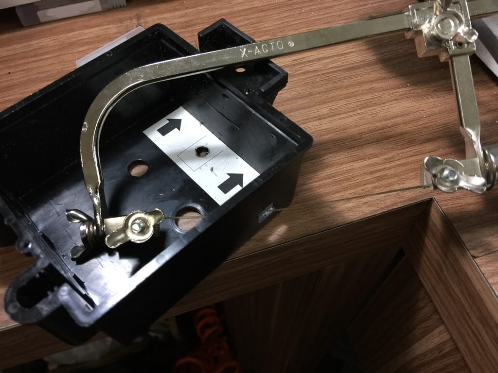
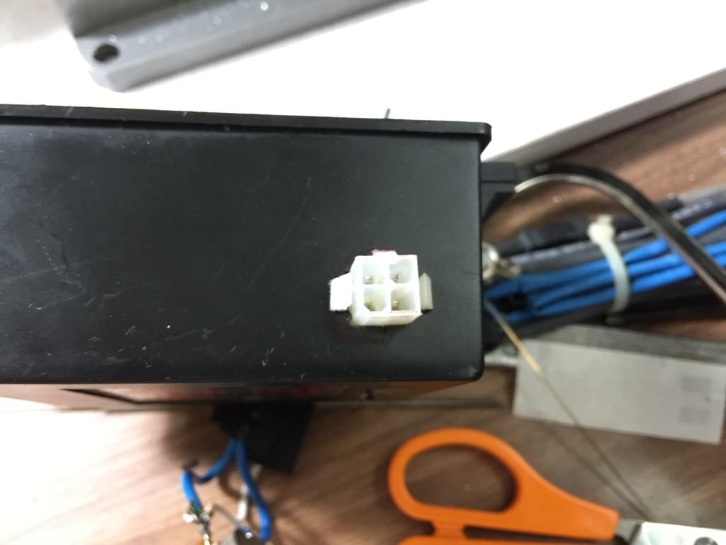
The process was straight forward enough, though I did encounter some difficulty along the way due to my inexperience milling something so small and mainly in filling up the board with components.  But I managed.  This is the board freshed out of the mill:
Picture
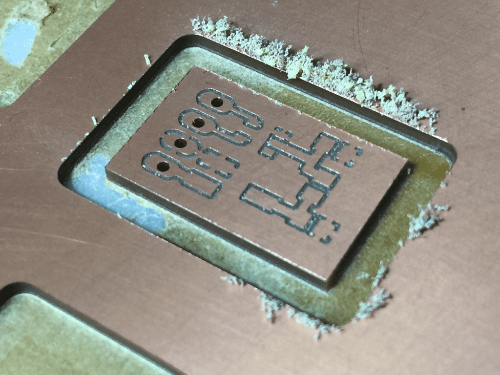
Fresh out of the mill
Picture
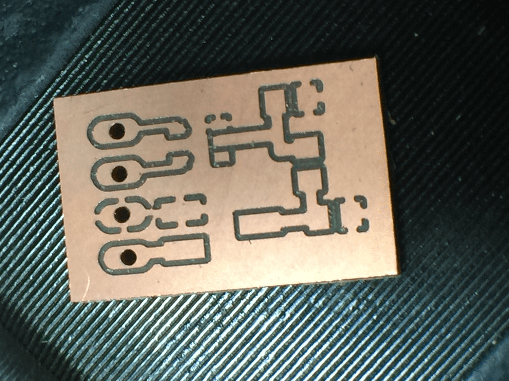
After cleaning up with sandpaper
To fill up the board with components, I've to make several purchases in term of equipments.  The cheapo soldering iron I have on hand made soldering SMD parts a terrible experience.  Since it was my birthday then, I bought myself some presents... lol. Excuses...
Picture
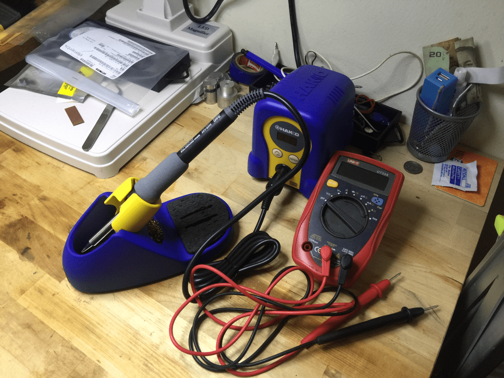
A Hakko FX888 soldering station
Picture
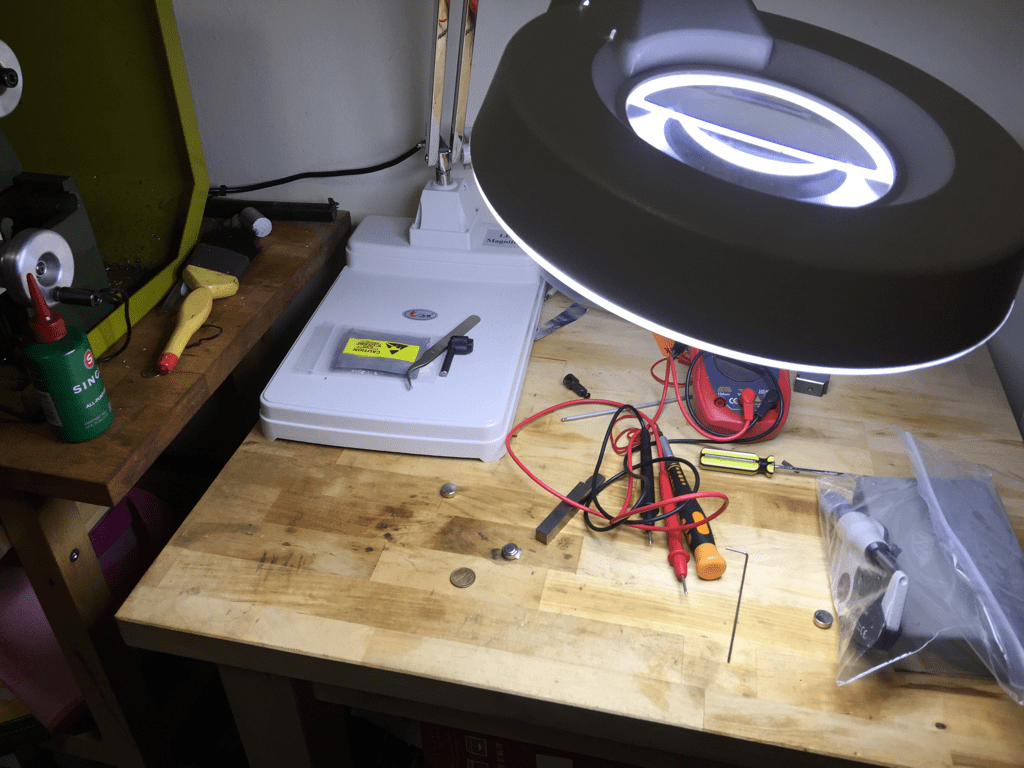
and this.... to assist my eagle eyesight when soldering the SMDs...
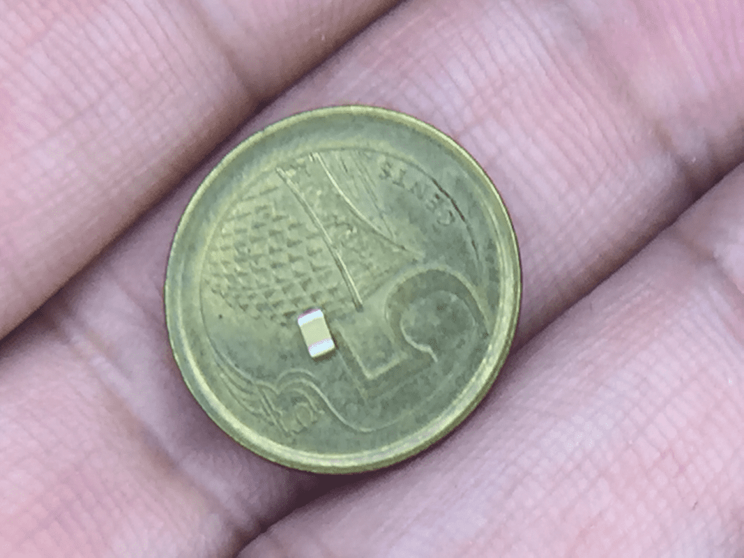
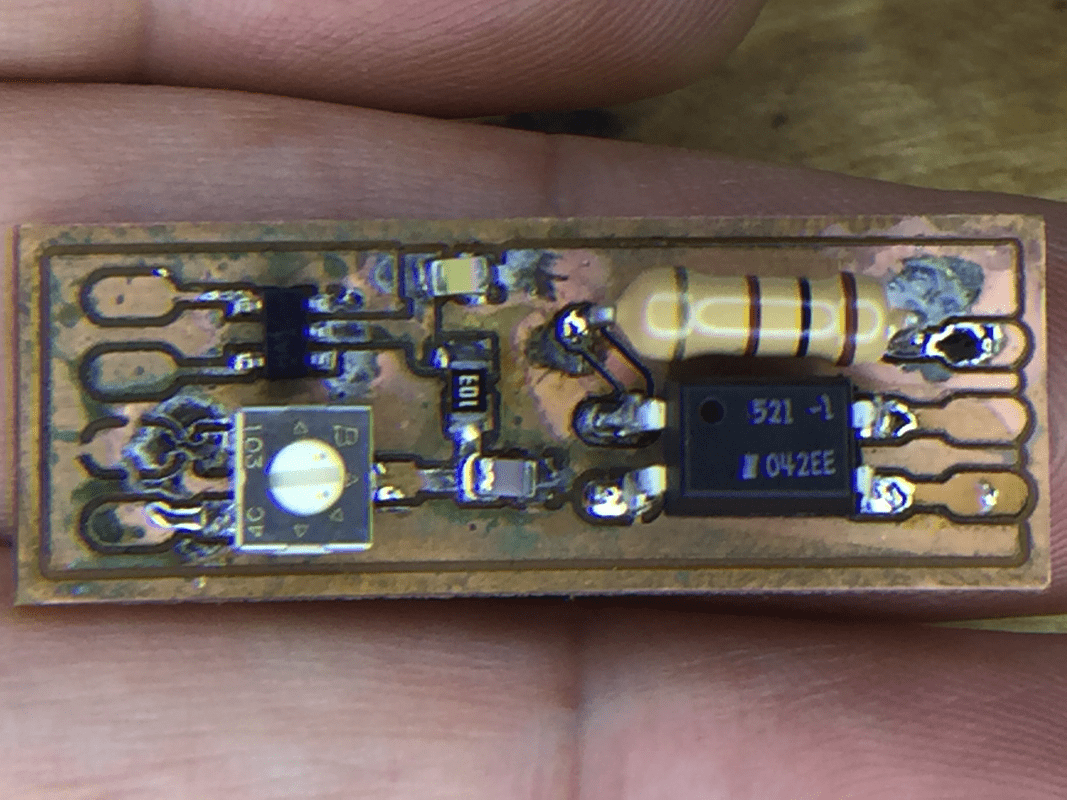
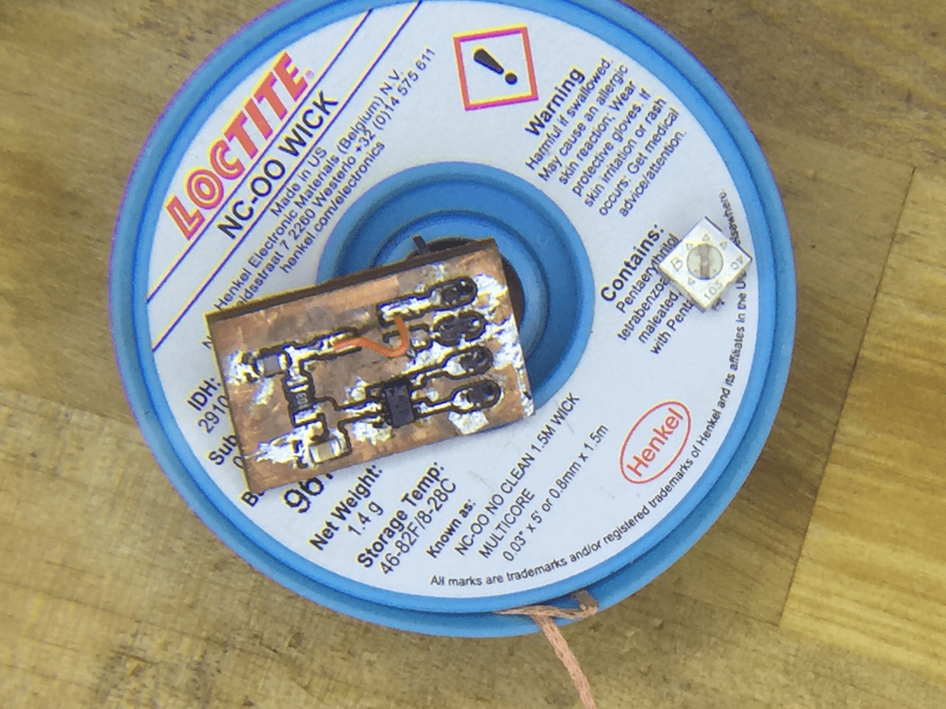
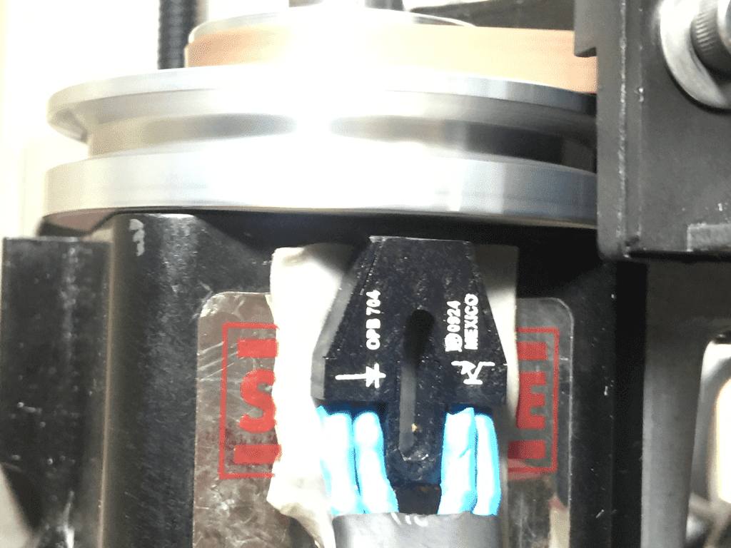
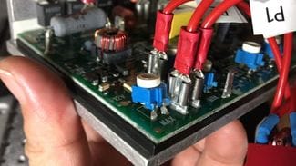
With the 2 bigger purchases and some little stuff like flux, I began filling up the board with components that are smaller than a grain of rice...  Under magnification, I can see that my hands tremble quite a bit when position the components.  The result, after several tries, is passable.

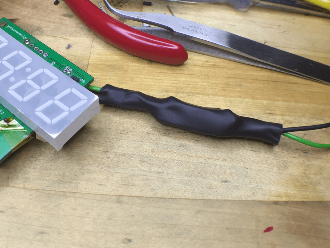
As the whole process was rather long, with lots of screw-ups mainly due to mistakes and stuff, I'll put the pics below and caption them as I go.  Hoover your mouse cursor over the pic for the caption.  Apologies for using this format to present the pics as I've problem selecting the many pics I've on my iphone and uploading it here.
A resistor... This pic was taken under the magnify glass I bought and with the iphone camera zooming all the way in.
The parts for the addon board. This board was the first version with the opto-isolator built in. We took it out later to keep things simple and need.
The board filled. The next step wiring the board to the main tach board gave me lots of problem. The 30 gauge wires kept breaking causing lots of frustrations. Further, I didn't realize that I shorted some of the pads during soldering.
The is the revised board. Basically the same as the earlier design but with the opto-isolator taken out.
The board added wired to the tach board. I resolder the wrapping wire so often that one of the pads on the tach board came off, together with the trace under the mask. Terence took over from here and wired up everything for me, together with another addon board he milled and filled.
With the board I made, I soldered on a set of header pins to use on the tach I'm working on, using Arduino Nano instead. It is working now but still on the breadboard. Will be milling out the PCB for it and use it on maybe my Proxxon Lathe.
The package from Terence came with some stickers for the spindle. This is pasted onto the under side of the spindle pulley. Saw this great trick to better do this job.
Sliding the sticker in.
Done!
The IR sensor is mounted to the spindle using heavy duty double sided tape.
As the index pin on the G540 may not be isolated, a opto-isolator is used. This is "cut off" from the board design in version 1.
Next is to connect it up to the tach board.
This board is easy. A tiny 68 ohm resistor and the opto-coupler. It is being wired to the tach board output on one end and G540 pin on the other. I'll be switching the connection from G540 to one of the input pins on port 2 of the USB Smoothstepper soon.
Shrink wrap it up to protect it against the environment, especially me...
Time to test it out. This and the next pic show the speed as commanded on the MDI after calibration was done. I had lots of problem between then and now just on calibration alone.
Nice... It is even better now but within 200 rpm difference is good enough for me, considering what I've been through trying to get it to work.
Finally, what I wanted few years ago came through, all because I've a good bro guiding and helping me along the way.  He guided me through several nights and helped troubleshoot over Whatsapp till 3-4am, on things like how to solder SMD, figuring out what went wrong when things didn't happen as it should.

I'll be making another tachometer using arduino, as well as making the sensor Terence did with another type of sensor.  All these will be for further learning and practicing.

I've just trammed up my wabeco mill today.  Should be starting with one of the manual machining projects which I wanted to start several years back.  This hobby kept my mind keen and not wander over negative things.  A little selfish though as I occupy of of the 3 bedrooms in my flat for it.  Both my teens are bulking together in the little room they have.  Sense of guilt?  Yes.  I need a solution to this.

I'm praying for a place with 4 bedrooms so that each of the girls can have their own room while I can still have my little cave to indulge myself in.  Lord, grant me my wish...
0 Comments

Spindle Speed Control

25/12/2016

3 Comments

 
I've been wanting to do this for a long time. Jeff Birt of Soigeneris, whom I bought the motion control system from, did a write up on the topic, but I just lack the courage to proceed, given my very limited knowledge in electrical works.  He did a PDF and have it posted on his website which you can view the PDF on his site here: http://www.soigeneris.com/Document/Gecko/Using_the%20Gecko_G540_VFD_Output.pdf.

​The idea is a simply one; using Gecko's VFD circuitry to output signal between 0V - 10VDC and feed that to the KBIC board. This replaces the existing speed control potentiometer.

From Jeff's writing:
Picture
Can't remember exactly when it all started, Terence and I was chatting about controlling the spindle through gcode. One thing led to another, he started doing research and put together the necessary components. His idea is slightly different from Jeff Birt's as he finds it necessary, for safety reasons, to cut off the the pot when operating on auto mode and the G540 when operating under manual mode.

This is what he came out with:

Picture
What he said makes sense to me; we have live voltage of 240V on one end. Any accidentally grounding will send a nasty shock to the operator or fry the KBIC board. Also, when operating in auto mode, there is no reason to leave the speed pot connected since the pot is no longer in control of speed adjustment.

With Terence around and doing the same, I mustered up my courage and went ahead with the mod.  Here is a brief write up on my journey, based on the little I understand when Terence was trying to explain to me.

If you have any questions on this mod, drop me a note, I'll ask Terence for his input if its beyond me...

​Here goes:

Picture
​Knowing that I'm a total idiot with electrical stuff, Terence made me these - a wiring harness, completes with printed labels. Maybe can sell as a kit for those interested. 

The DB9 connector is for my Soigeneris' control box, which brought out the VFD to its back panel for neater connection.

The "kit" looks rather nice, much nicer that some of those I bought from companies abroad.


Some pics were taken before I start meddling with the components within the box.  Tend to forget what goes where after removing stuff...
Preparing the box
Terence provided a sticker to mark out the hole location for the switch.  I screwed it up by pasting it more to one side... 

The square hole was more of a challenge to me.  So I decided to rough it out on the mill and finish it off with either a file or the jeweller saw.  As the plastic box flexes quite a lot, 2 pieces of wooden blocks were used to support from the bottom.  Quite a bit of filing was needed before I managed to squeeze in the molex connector.

Connecting the wires
Connecting the speed pot to the switch.  Basically just a follw the label and insert the connectors operation.  I'll have to slap myself if I screw up even this... 

I've forgotten to take pics while putting back the board to the box.  Its a tight squeeze but everything went in without a problem.
Picture
Picture
Picture
Having the ability to control the spindle speed in my gcode is really a dream coming true, all thanks to my buddy Terence.  The mod has yet to be completed as we need to tell Mach3 the speed the spindle is spinning at (calibration) so that it knows how much to put out for the speed commanded.  So the next part of the project involves making a tachometer that reads the spindle speed and output it to both the LED display as well as to Mach3 via its Index pin.  It is a tougher part for me as it involves electronics work.  But so far I managed, with lots of help of course! lol....

This stage was made so easy because of the fact that most of the things were done for me with the kit.  It turned out to be not as scary as I envisaged it to be.  Let me know if you are contemplating to do the same.  Send me some pics if you may, while doing it.  I'll post them up.

Meanwhile, have a 
Merry Christmas!!!
3 Comments

    Enter your email address:

    Delivered by FeedBurner

    Categories

    All
    3d Printer
    Er32 Collet Chuck Proxxon
    Misc
    Misc Projects
    Projects
    Proxxon Pd400
    Sherline / A2Z Monster Mill
    Things I Bought
    Wabeco Mill

    Archives

    June 2018
    January 2017
    December 2016
    August 2015
    July 2015
    June 2014
    May 2014
    December 2013
    November 2013
    October 2013
    June 2013
    March 2013
    February 2013
    November 2012
    October 2012
    September 2012
    August 2012
    July 2012
    June 2012
    May 2012

    RSS Feed

Powered by Create your own unique website with customizable templates.