Wongster's Production
Share it on
  • Home
  • Blog
  • My Old Blog
  • My Shop
  • Resources
  • About Me...
  • Contact Wongster

A Thought on Holding The Rollers

18/7/2015

0 Comments

 
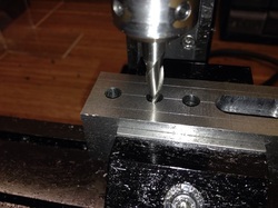
When I was just about to get out of bed, the ER collet holder I bought from Arc Euro came to my mind. So I scrambled to the shop and search for it.
Picture
Picture

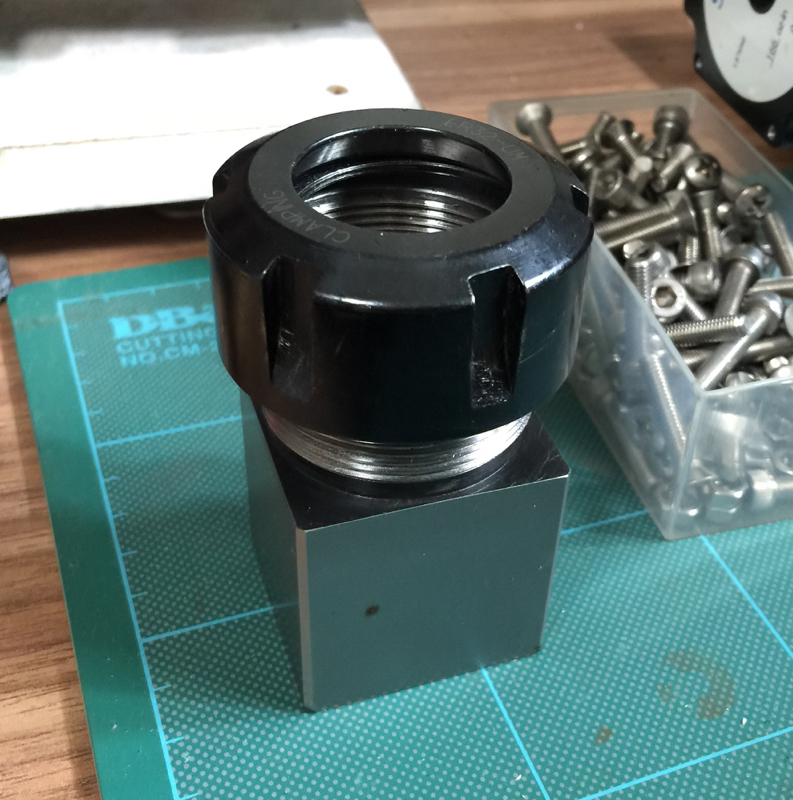
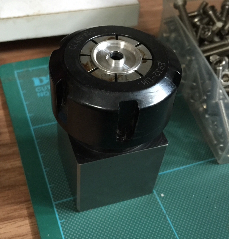
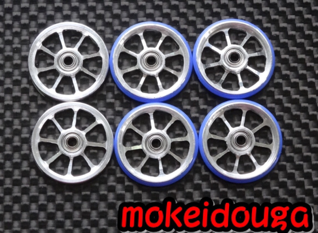
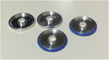
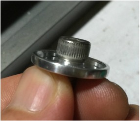
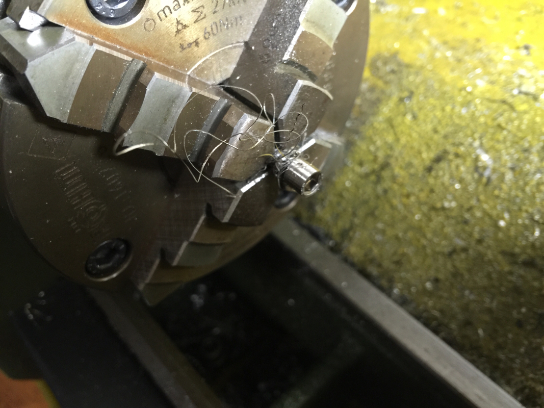
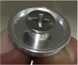
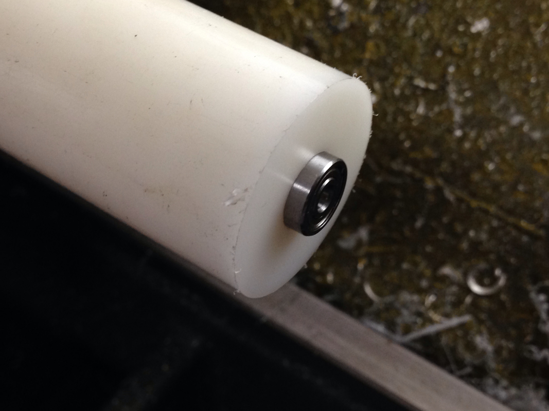
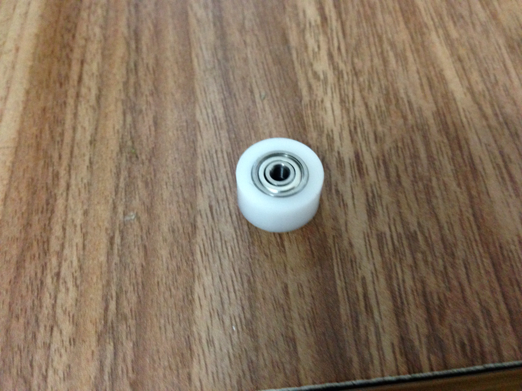
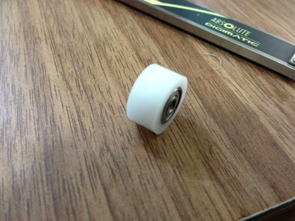
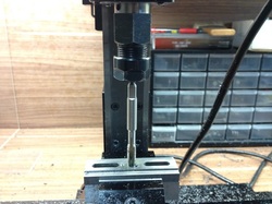
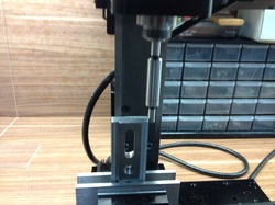
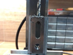
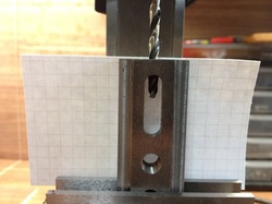
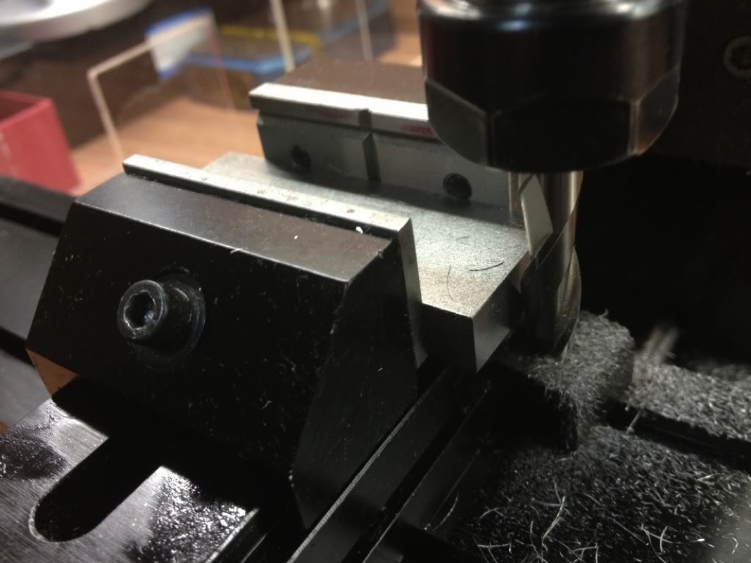
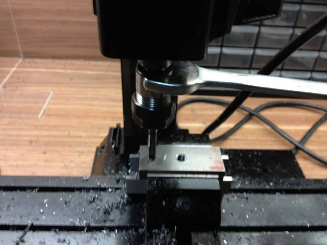
I tried out using the 19mm collet but the little thin disc fell right through. So in tightened the nut and carefully put in the roller till it started gripping. The problem using this method of holding is, I'm not sure how to hold it such that the working surface is perpendicular to the spindle. Further, I'll have problem with those pieces that have the blue plastic ring on their parameter.

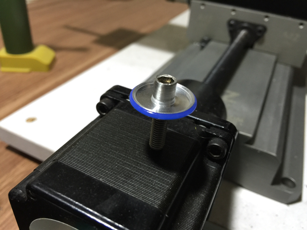
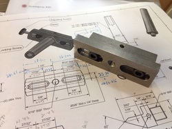
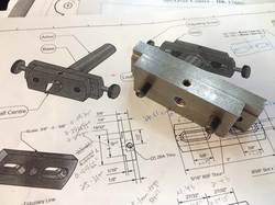
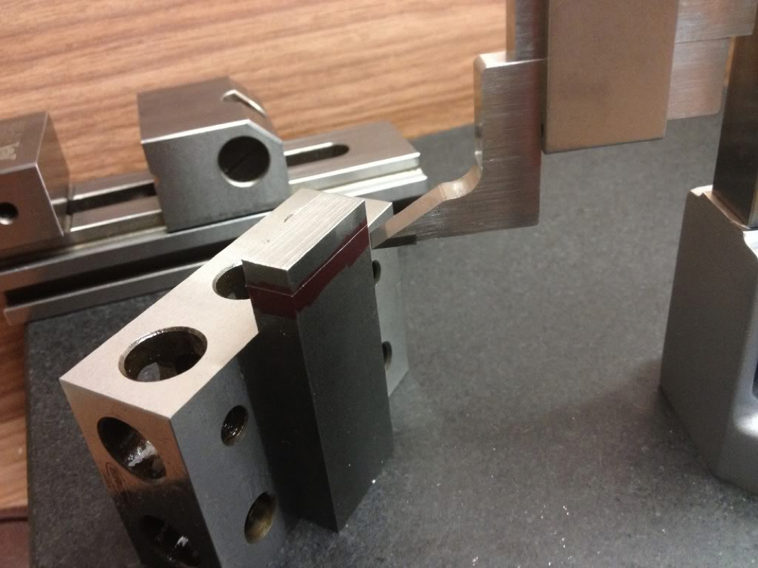
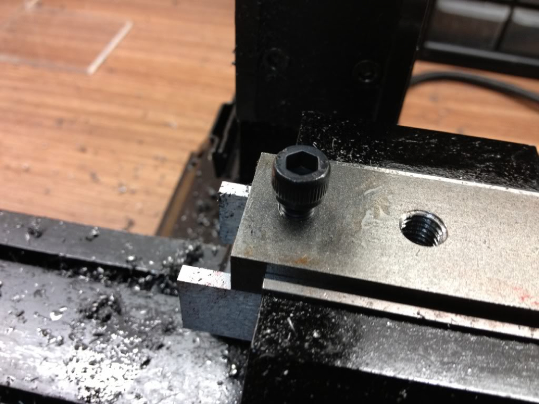
Looks to me that holding the rollers via the centre hole is the way to go.

If anyone has any suggestion, please comment. Thank you.

0 Comments

Slot Car Rollers

17/7/2015

2 Comments

 
Been wanting to get back to the shop for the longest time. My last post to this site was about 2 years ago... Anyway, blame Terence, whom has been showing off his work.

A young man contacted me on Carousell asking if I'm also into CNC. He would like to customize some wheels, which are used as rollers on his slot car. From what I understand from him, the rollers would ride against the wall of race tracks, guiding the car along the track.

He forwarded me some pix:

Picture
Picture

He bought some blanks and would like to have them machines tongue design he wants. We chatted thru Carousell and migrated to Whatsapps with pix flowing to and fro. Based on what was told to me, i put them into 3D models.

Picture
Picture

But I find the spokes too thin at 1mm. So I reduced the number of spokes to 6 instead.

Picture
From his response, I know that he still prefers having 8 spokes than 6. So I went back to the drawing board and made some adjustments:
Picture
After having dinner with my girls at an overcrowded Korean BBQ restaurant at SOTA, I went by the young man's place to pick up the blanks.
Picture
Don't ask me why some came with the blue plastic ring and some don't. I don't know anything about slot car till now.

I imported the 3D model into BobCadCam and extracted the bottom edges. The features I'll be working on are the spokes since I'm given the blanks. After computing the toolpath, I ran the simulator to make sure.

Picture
Picture
I'm giving the rapid height a bigger value to clear the cap screw which I plan to use to hold the wheels.

Next will be to find the right sized capscrew to use. The centre hole is slightly less than 5mm, which is to be used to press in a 520 bearings. M5 capscrew seems about right but there is some tiny bit of movement. Also, the capscrew head is a tad too big. I've it turned down to just slight more than 6mm.

Picture
Picture
Picture
Terence suggested I try using a countersink screw as it would centre itself to the countersink.. As I do not have a suitable one, I'll make a trip down Kelantan Road sometime next week.

Just to have a feel of how it would look:

Picture
Ok. That's all for now. I'll see if I can get some work down tomorrow cutting some blanks to test. Wouldn't want to try it on the actual thing.

Meanwhile, Be blessed!

2 Comments

Mini Kossel: Carriage Wheels

18/11/2013

0 Comments

 
The trial in making the wheels started on Saturday and Sunday for a couple of hours each day.  Some pix were taken but I didn't have the time to update the blog till now.  Just returned from the A&E of Changi General Hospital which we spent the last 4 plus hours waiting for the doctor to administer treatment to my poor little Ruth.  Her fever went back up Monday night and she started bleeding from her left nose.  We panic and drove her straight to A&E after midnight.  The wait was rather long with more time spent waiting for the result of her blood test to be out.

Ruth is such a brave girl.  Despite the pain and discomfort, she allowed the doctor to draw blood from her without once pulling back her arm.  I'm so proud of her!

As I was to send our helper to the airport in about 2 hours time for her trip back to Myanmar, I gave up the idea of sleeping - and so this blog entry.

Terrace provided me with a length of delrin of about 28.6mm diameter.  I felt bad as it will be such a waste of the expensive plastic as the final diameter of the wheels will only be 15mm.  He explained that it was meant for another project of his which didn't happen and so using it for this purpose - felt so much better after learning this.

On with the pix.  
Picture
A short section was chopped off at the bandsaw and chucked into the lathe. Both ends were faced. As the material is softer than what I usually play with, I went straight with the 3/8" drill. It cut through like butter!
Picture
Next came boring to ID of 10mm to fit the bearings. I target at 9.95mm to press fit the 2 bears into it. I wanted to try using the boring head I bought from CTC Tools but the dial to adjust the boring head was facing the wrong side if I want the clamping capscrews to face up. I may have use the tool the wrong way. Will study it further.
Picture
Next I tried putting the boring tool on the QCTP Tool Holder. After setting the height, I find that I can fit it into the hole... Its too big...
Picture
Setting the face of the QCTP square to the faced workpiece.
Picture
I ended up using the micro tool bar my Irish friend bought on my behalf and shipped over. This little tool works very well but a tad too short for this job. So I've to go one wheel at a time.
Picture
Test fitting the bearing.
Picture
Working on the OD. I didn't expect myself to be able to hit 15mm exactly! At least that was what my 2 decimal places Mitutoyo Digital Caliper said.
Picture
Parting off with the insert tool.
Picture
After parting off.
Picture
After facing off the other side, the first bearing was fitted. I pressed it in simply using a 123 block. Easy job.
Picture
2nd bearing pressed in. To remove the bearings, I've to use a pin big enough so as not to damage the bearings to tap them out.
The next ops is to turn the chamfers on each side of the wheel so that it seats nicely in the slot of the aluminium extrusion.  The plan is to cut all the 18 pieces needed for the mini kossel and turn a shaft to hold them each at a time.  I've yet to think of how to turn the chamfers accurately for it to balance itself in the slot like the cross section pix below.
Picture
I'll figure that out when I feel better.  A little under the weather myself...

Be blessed!
0 Comments

Hemingway Set-Over Centre: The Base - Complete

29/10/2012

0 Comments

 
I continued with the work on the Base and completed it over 2 sessions of about 2 hours each.  I took it very slowly when milling the other slot with a 10mm slot drill due to the vibration and loud noise.  The feel on the handwheel while feeding didn't feel smooth at all.  This may be caused by the ER16 spindle chuck I'm using which extended the tool out quite a bit.  I didn't have that problem when using the Sherline's endmill holder but the largest holder I've from Sherline is 3/8"...  Some rectification was done to the Slide's slot as one side is tapered.  The 2 components now fit nicely together and the sliding one against the other is smooth.  4 more parts to complete before I can call this done.
Picture
Moving over to the start. The more I use the mill, the more confident I get in getting to the spot I want using the handwheels. The right limit of the slot was set with the tool maker's clamp on the right of the job against the saddle.

Picture
Moving to the left limit and setting the clamp.

Picture
Milling the 1/4" slot with the Sherline 1/4" slot drill. The Sherline's endmill holder in use here.

Picture
Slot done.

Picture
The 10mm slot drill in the ER16 collet chuck was employed to cut the counterbore slot. To set the depth, I plunge the slot drill to the depth of 1/4" and fit another piece of the toolmaker's clamp on the column bed.

Picture
Slot done. I went at 0.25mm per pass to minimise vibration. The cap screw sit flush with the top surface of the Base.

Picture
The centre hole enlarged to 6.4mm to tap 5/16" BSF.

Picture
Testing fit. No side wobbling encountered. I'm pretty pleased :)

The instruction calls for the 2 x 2BA holes to be done on the drill press.  I was running out of time to set up the drill press (its under the bench...) and so stand the part in the vise and carry on.
Picture
Locating the side and dialed to the centre of the workpiece.

Picture
Centre drill and drill through with a 4mm. I'm at the limit of the z travel...

Picture
A piece of card stock used at the back to check if I'm right in the middle. Not too bad..

The part was then flipped over to drill and tap the other 2BA hole on the other side.  This completes the work on the Base.
Picture
View from the back where the 2MT Arbor will be screwed in from.

Picture
The front. I'm wondering if the screws are a little too long. The drawing shows them as almost flushed with the surface. Can those who did this confirm if I need to shorten the screws?

The rest of the work will be mostly done in the lathe.  From the plan, I'm left with making the 2 adjustment screws, the Centre, and the 2MT Arbor.

I'm hoping to get back to the shop real soon!

Blessings to ALL!!!
0 Comments

Hemingway's Set-Over Centre: The Base

29/10/2012

2 Comments

 
The Set-Over Centre is the 2nd kit I bought from Hemingway Kit. The first was the knurling tool which I've not the confident to start working on. Maybe after a few simpler projects I'll start my attempt.

Like most of the little projects I did, I've the drawings drawn on my notebook as 3D models so that I can visualise how things fit together. The raw materials were cleaned up and cut to size to prepare for marking.

Enough of writing. Time for pics...
Picture
I measure the thickness of the steel stock and realised that it is not the 3/8" as shown in the drawing. Same goes for the width, which is narrower than the 1" dimension given in the drawing. I supposed these are not critical.
Picture
Cleaning one side of the stock to use as reference.
Picture
Marking out the other end to mill stock to length. This was the maiden "scribe" by my brand new Mitutoyo Height Gage.
Picture
I can't be more than happy with what I see on the caliper. This is important to me as I've not been able to "hit the mark" on the mill since I started the hobby. Hoping to see more accurate work!
Picture
Marking out the holes and the area to be milled. I used the permanent marker as "layout fluid". Tried shipping in Dykem but my order was held in US and can't be shipped.
Picture
Need to improve on using the punch. Would the optical punch help? Tried correcting by "moving" the punch marks as shown in some YouTube vids - not much of an improvement.
Picture
I was wondering if I should use the edge to move to the centre mark but decided to try using the Mitutoyo Centre Finder. Not really sure of how to use it though. With the point in the punch mark, I adjusted the handwheels on both the horizontal axes till I feel the Centre Finder smooth at the moving part. Anyone can share how this is to be used?
Picture
Centre drill...
Picture
Drilling with 6.4mm drill for 5/16" BSF. Took quite a while to drill through. There was quite some vibration felt during the process, prompting me to reduce spindle speed and ease the feed.
Picture
Hole done. Not very round isn't it...
Picture
Tapping the hole. The spindle with a dead centre was used to start the thread.
Picture
Countersink used to deburr the threaded hole. Should I be doing this before tapping?After finishing with the centre hole, I moved along X axis on both side of it for the 2 1/4" BSF tap holes. The 1/4" BSF tap doesn't have a hole at the end of its shank. So it went into the ER16 collet held in the spindle as guide.
Picture
The Z axis was lowered while the tap was turned using a wrench on the collet chuck.
Picture
Thread done and tested with a 1/4" BSF cap screw that came with the kit. I don't have anything BSF at home to test the 5/16" BSF though. It is meant for the threaded end of the half centre.
Picture
The surface was then cleaned of chips and oil. I redid the layout of the recessed area as the dye of the marker was washed away by the cutting oil.
Picture
I was a little nervous when milling the recess. My last work in steel making the flycutter was quite a painful one; the Sherline mill vibrated like no tomorrow and it was really loud!
Picture
It wasn't that bad this round. Each pass was only 0.2mm deep. After reaching the final depth of the recess (1/16"), the slot mill was moved to open up the slot above and below the centre line at full depth but with rather slow feed and speed. Conventional milling was used.
Picture
The recess completed. I measured the slots and found that I've one end at 15mm while the other end is at the correct width of 15.08mm. Is my horizontal axes not perpendicular to each other? Also, I went 0.07mm to deep though I dialed in the correct amount. I'll do the adjustments when making the Base.
Picture
The top was drilled and tapped for 2BA setscrew, right to the 5/16" thread hole.
Picture
The setscrew installed. You can see that it is not exactly at the centre of the 5/16" thread hole. Don't think this will cause problem.
Picture
The Slide is now completed. I may not want to mill the radius at the 2 ends of both the Slide and Base to simplify the build. Maye I should, to learn how this should be done.
I'll work on the Base in my next session in the shop. One question which I would like to ask. The 2MT arbor needs to be machined and thread 5/16" BSF. I'm scratching my head thinking through how I should be holding the arbor. The Proxxon lathe has a 3MT in the spindle. My Sherline lathe has 1MT. Do I hold it between centre?
2 Comments

    Enter your email address:

    Delivered by FeedBurner

    Categories

    All
    3d Printer
    Er32 Collet Chuck Proxxon
    Misc
    Misc Projects
    Projects
    Proxxon Pd400
    Sherline / A2Z Monster Mill
    Things I Bought
    Wabeco Mill

    Archives

    June 2018
    January 2017
    December 2016
    August 2015
    July 2015
    June 2014
    May 2014
    December 2013
    November 2013
    October 2013
    June 2013
    March 2013
    February 2013
    November 2012
    October 2012
    September 2012
    August 2012
    July 2012
    June 2012
    May 2012

    RSS Feed

Powered by Create your own unique website with customizable templates.