Wongster's Production
Share it on
  • Home
  • Blog
  • My Old Blog
  • My Shop
  • Resources
  • About Me...
  • Contact Wongster

Turner's Cube - Part 1

26/10/2012

6 Comments

 
It was a fun morning in the shop today with Terence coming by to do some work together.  We have been discussing on doing some projects together and wanted to start with the Touch Probe for the CNC mill he drawn up.  As he has no experience in turning (not after leaving Secondary School many many years ago), we settled for the Turner's Cube as the starting project.

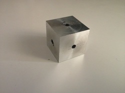
This is how a completed Turner's Cube looks like, taken from Bob Warfield's CNC Cookbook:
Picture
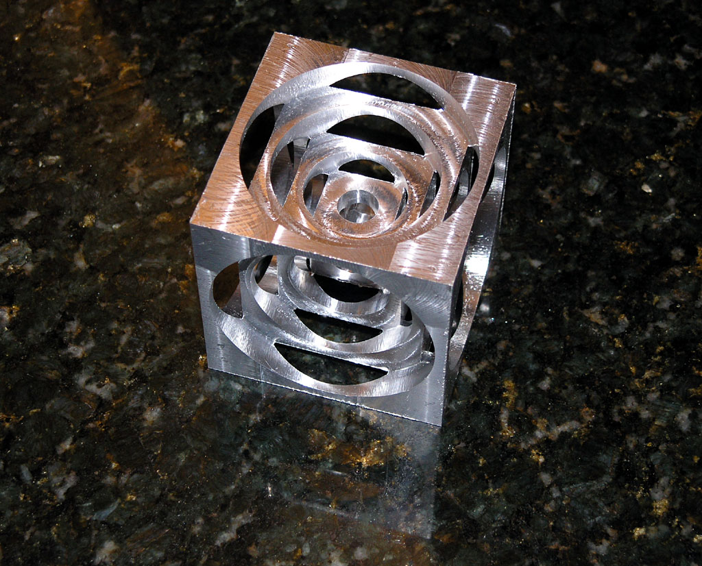
Click on the pic to go to CNC Cookbook. Bob has many interesting articles on machining and is the author of GWizard Calculator - a really helpful tool to have even for home machining.
It is a simple beginning project, I read online, for most people.  There are many videos and pictures on the net showing different versions being made, not just on the lathe, but also on the mill.  This project will be a good one for Terence to gain some hands on with the lathe and for me to learn the entire process from planning to completion and to build up the required confidence.

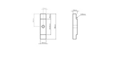
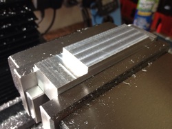
We started with a square bar of 1" aluminium I've in the box.  To keep things simple, a smaller cube was agreed upon.  Some time was spent facing the sides to bring the cube down to 24.5mm.  Keying that in the GWizard Turner's Cube calculator, the other dimensions were given.

We didn't get to finish the project in one session as I ran out of shop time (meeting my parents to visit my grandmother).  Hope to finish it up in our next session.

Not many pics this session.  We were chatting away while I show the big guy some basic lathe work, which is all that I know... We hope to learn together, motivating and teaching each other up the learning curve of machining.
Picture
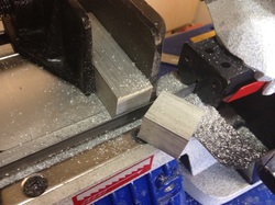
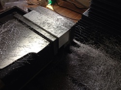
The 1" square aluminium bar stock of unknown grade being cut in the bandsaw.  It was a quick cut with feed set at 'M'.

Picture
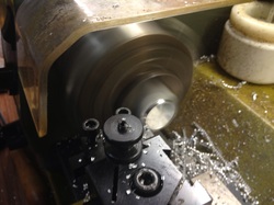
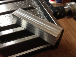
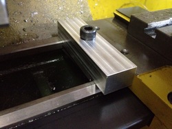
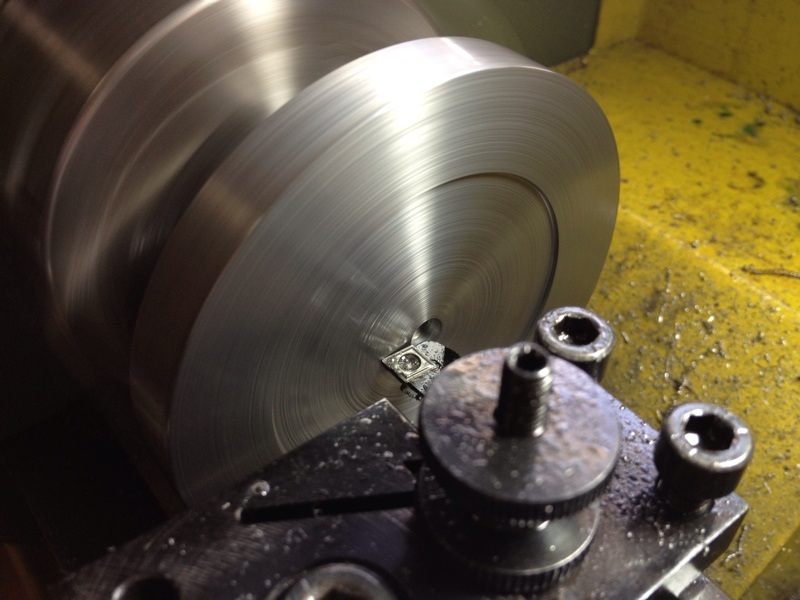
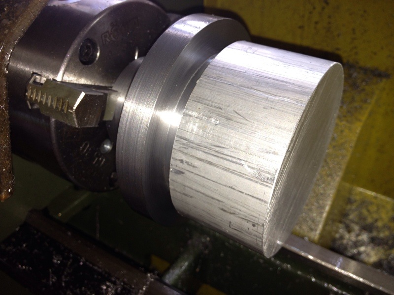
The workpiece was then cleaned up in the lathe using the automatic 4 jaw chuck.  I really love this Rohm chuck - very good in precision despite being a scroll chuck.

Picture
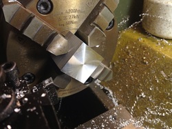
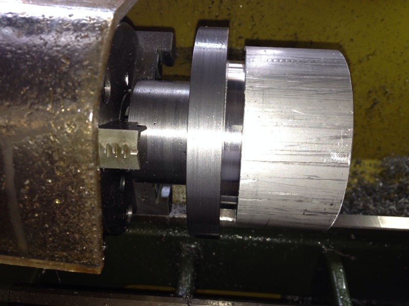
Couple of sides done.

Picture
All sides done and ready for the next stage.

Picture
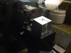
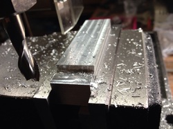
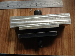
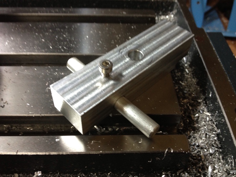
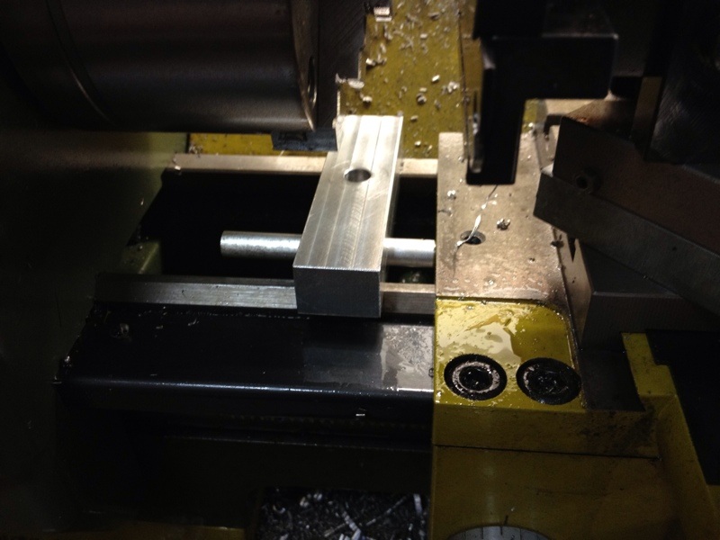
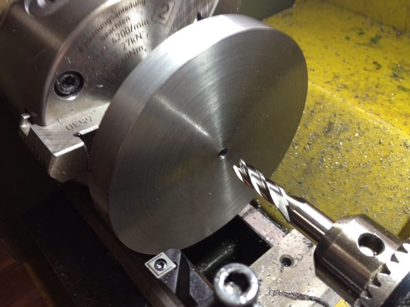
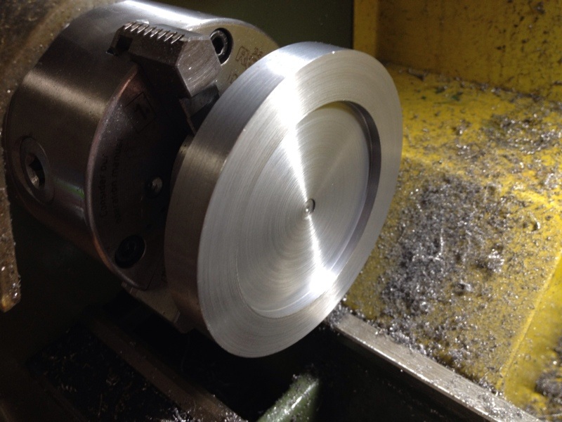
The first drill called for in the GWizard Calculator is a 3.5mm drill.  Terence suggested drilling each side till half the depth so that if the cube is not in alignment with the centre line during chucking, we'll still have the holes in the middle of each face.  It is a very good idea and makes lots of sense!  I would have drill all the way through on 3 sides to save time.  But the result proved the added step to be unnecessary as all the halves lines up very nicely with each other!  I was surprise with the result, adding to my confident with the lathe and the Rohm chuck.

This was where we stopped.  A total of slightly less than 4 hours was spent in the shop, including chit chatting, introducing the lathe and parts, deciding if the mill or the lathe should be used for the ops, and the actual work. 

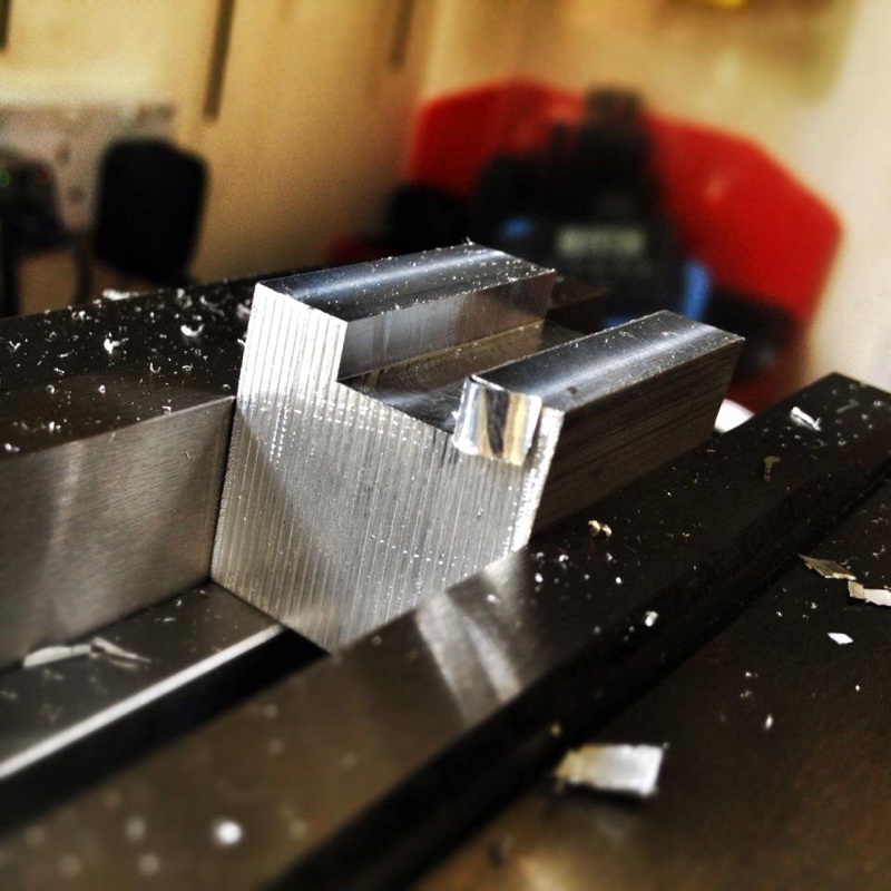
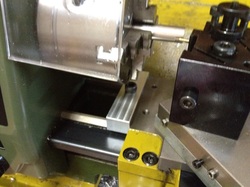
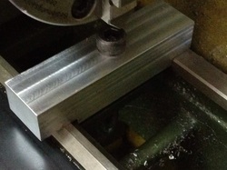
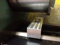
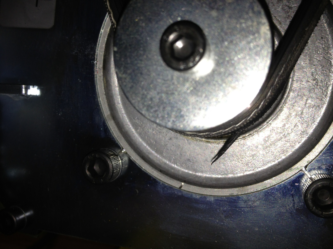
Before Terence left, I took the opportunity to show off how deep the Wabeco F1200 can cut in aluminium in one pass.  But being a "chicken", I dialed in only slightly more than 4mm depth and did the cut with a 10mm HSS endmill.  Some chatter was felt (and heard) when I was feeding slowing (chicken enough?).  As I increase the feed with the handwheel, I realised that the mill can in fact be used more aggressively given its rigidity.  I read from Wabeco's instruction manual that it can take, without any problem, cuts up to 10mm deep in steel with a 10mm endmill.  Wow....  But I wonder if that is possible with my MT2 spindle bore.  On hindsight, I should have pay for the ISO30 tool holding option, which is another EUR 158.82...
Picture

A video of the cut, taken by Terence.
6 Comments

Z Axis Coupler - Second Attempt

26/8/2012

0 Comments

 
I planned last Saturday for a good long session in the shop today to make the stainless steel bushings for my dad and to make the couplers for the Portabee. As of yesterday late night, I know that it'll not come to pass when my mum called saying my grandmother has been warded. We were over at the hospital visiting her till past midnight, reaching home bashed.

This morning, I spent about half an hour in the shop to complete a piece of the coupler for the Portabee. As I ran out of aluminium of the right size, brass was used instead. Machining brass is such a joy and I went absolutely coolant free. Tapping the M6 and M3 presented no challenge at all. I don't know if it's the effect of the 2 new HSS taps I got from Mike or it is just the nature of brass. And, no additional effect is required to make brass look great.

This is how it looks installed:
Picture
I'll be machining 2 flats to aid in tightening the nut against it.
0 Comments

Simple Carriage Stop

25/7/2012

0 Comments

 
As I'm to make 50 pieces of the stainless steel bushing for my dad, I'm thinking of a way to make turning to a specific length easier and more repeatable.  The carriage stop has been on my To-Do list for a long time.  But I just couldn't find a plan online that can be used on my Proxxon PD400.  The Fixed Steady I've gave me an idea though - a simple piece that clamps onto the ways of the lathe to act as a stop.
Picture
I measured the distance between the ways and the dimensions at the base of the Fixed Steady to come out with a simple diagram.

Picture
A pieces of square aluminium bar stock was used.  All faces were cleaned up and milled square.

Picture
All squared up and ready.

Picture
Milling a section 3.5mm deep.

Picture
The other end that will sit on the prism shaped way.

Picture
The assembly.  As mentioned above, the clamping plate is from the Fixed Steady.

Picture
Placed on the way to see if it holds out.

Picture
Then I realised one thing; most of the job will be done close to the chuck.  

Picture
It is, in actual fact.  I'm not able to tighten the cap screw with the allen key in this position. 

Picture
Switching to a hex head solved the problem.  Tightening is also easier with a wrench.

I carried on working on the stainless steel bushing with the stop in place.  It works rather well till a long string of swarf went in between the stop and the carriage.  This got me thinking of those pics of carriage stop I saw online.  The rod that is used on most for adjustment may be the solution to my problem since contact area is smaller.

Back to work on the mill drilling and tapping the stop.  This is what I got:
Picture
Picture
After making 2 more pieces of the bushing, I started wondering how have I been surviving without the carriage stop...  It is a simple to make, yet effective.  It makes working on the lathe so much simpler.  If I'm able to make one that will trigger the autofeed to stop, it will be even better.  The plan posted on Tools And Mods by Ralph Patterson looks simple to implement.  The plan is available for download here.  I'll study the plan to see if its simple enough for newbies like me.

Time to stop.  Now feeling that good.  The swell on my cheek doesn't seem to go away.  The stitched wound on my gum feels sore.  Guess I should wash up, make something to eat, take the many pills given to me, and go to bed.  I've a meeting to attend at 11am tomorrow.  Fixed that up last Friday.  Will continue my medical leave after tomorrow.
0 Comments

Noise in Gear Box

26/5/2012

0 Comments

 
The lathe has been making some noise in the gear compartment when the spindle is spinning. this morning, while waiting for my dearest to get ready to send me to work, I opened up the gear box to poke around a bit. I saw this:
Picture
and this:
Picture
The belt was taken out for the photo shoot.
I cut off the frayed rubber with a pair of scissors and the noise went away.

The lathe has been with me for less than 6 months. It is clocking about 2 to max 4 hours of use each week. Time to change them? Seem too soon for any belt change, especially with my level of usage.
0 Comments

ER32 Collet Chuck - Recess for the Register Completed

20/5/2012

0 Comments

 
I was up as early as 7am this morning.  Wanted to sleep in on this Sunday morning but just could not.  After washing up and 2 cups of coffee, I started working in the shop.

The job of the day is the recess at the back of the chuck which needs to be precisely done so that it fit the registration boss on the spindle flange without any wobble.  I asked Dave my last couple of questions on the forum so that I've clear images in my mind of how I should carry out this operation.

Not much pics taken as the session was rather short.  I was concentrating intensely when bring the recess to its final size.
Picture
After starting a shallow hole with the centre drill and 5mm drill, a slightly larger endmill was used to open up the hole a little more.
Picture
The Sherline insert boring tool was used to open up the recess to slightly more than 60mm. This is to leave some "meat" on the wall of the recess after I get close to the depth.
Picture
The gauge made earlier was used to test the recess bore. It fit nicely but the air within the 2 mating parts refused to let the gauge sit properly. I tapped it in with the palm of my hand and couldn't get it out after. It has to be pried out carefully with an allen key.
Picture
From another angle. The shiny part is the gauge.
Picture
All done for the recess. I let it cool before testing it again with the gauge. I believe the air pocket formed is an indication that the fit is a good one. I definitely hope so.
The "floor" of the recess was finished off as best as I can.  It feels smooth now but doesn't have the bling shown in Rob's and Dave's pics in the forum.  It makes me wonder if its the camera as mentioned by some other members of the forum. Mmmm... 

Next up, the mounting holes.  The 3 holes are clearance holes for M6 cap screws.  After completing the recess, I suddenly realized that I have forgotten to scribe the PCD for the mounting holes... All is not lost, me think.  I've on order from Little Machine Shop in US a set of M6 Transfer Screws.  The recess will help to locate the collet chuck while I tapped the part to transfer the hole locations.

This is how the set of Transfer Screws looks like, for those whom I tried asking if they're available in SG.
Picture
Pic taken from Little Machine Shop.
The threaded portion is to be screwed onto the mounting hole on the spindle flange, leaving the little pointy portion sticking out.  The collet chuck will then be placed onto the flange using the recess as a guide.  It will then be tapped with a mallet to have the hole positions transferred to its back.

But I'm still concern about one thing; will the trapped air causes the collet chuck not seating properly affecting the transferring of hole locations to be off?

I'll know when I received the item, together with a 3" angle plate.

That is all for today.  Have a blessed week ahead with unceasing fruitfulness!  Shalom.
0 Comments

    Enter your email address:

    Delivered by FeedBurner

    Categories

    All
    3d Printer
    Er32 Collet Chuck Proxxon
    Misc
    Misc Projects
    Projects
    Proxxon Pd400
    Sherline / A2Z Monster Mill
    Things I Bought
    Wabeco Mill

    Archives

    June 2018
    January 2017
    December 2016
    August 2015
    July 2015
    June 2014
    May 2014
    December 2013
    November 2013
    October 2013
    June 2013
    March 2013
    February 2013
    November 2012
    October 2012
    September 2012
    August 2012
    July 2012
    June 2012
    May 2012

    RSS Feed

Powered by Create your own unique website with customizable templates.