Ever since I started with mounting the iGaging scales on the Wabeco and Proxxon, I always wanted a better way to make steel brackets for the read heads. Of course I can use the vise and hammer steel sheets to shape but having a sheet bender or brake would make nicer looking brackets. Came across Mogens Kilde's website (which I believe is no longer in operation) in August of 2015. He has a pic of a completed sheet bender of a suitable size for my tiny shop. It measures only about 300mm across and it looks real good in the pic. So I went ahead and purchased the plan for USD4. The plan was emailed to me a couple of days later in the form of a PDF. But many things happened since then that I was drawn away from the shop.
Few weeks ago, I started wondering if I should start a few projects. This will help in revising what I've learnt from the many generous folks whom had, one way or another, taught me about machining.
Like all the projects I've done so far, I always like to model them in 3D CAD so that I've a visual of what I'm doing and plan my approach. This has been my habit given my little experience in the hobby and it is regardless of whether I'm going manual or CNC.
I've not started work as my shop is still in a mess. But the CAD has just been completed.
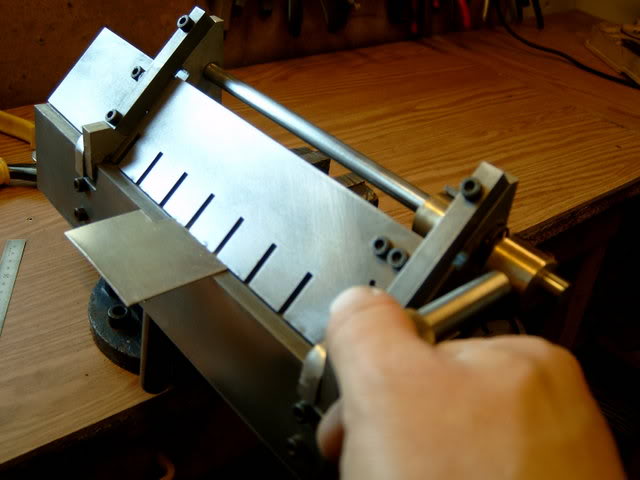
First, the pic from the man himself:
I started modeling the components in Fusion 360, thinking that I can use this project to learn how to use this powerful yet free for hobbyist software. All components were done but I encountered difficulty in "assembling" them using the "Joint" command. I sought help from the official forum and got a very quick reply with a YouTube video on how to specify multiple joint of 2 components. I still find it difficult to use and redo all the components in Solidworks, my favorite software.
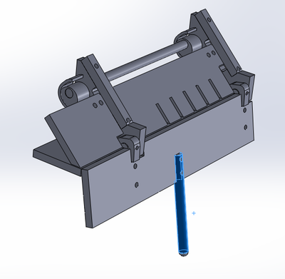
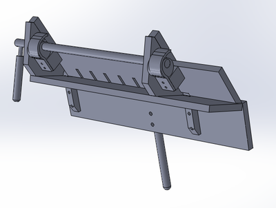
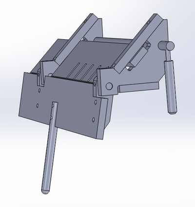
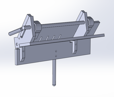
This is the result after assembly:
This is the result after assembly:
While modeling the parts, I took note of the challenges I'm likely to encounter when I start work. One would be the "fingers" of the sheet clamp. If the end of the slots has to be square for whatever purpose, I'll have to file them to shape by hand. Don't have any endmill that can cut 25mm deep, especially when each slot is only 4mm wide. The odd shaped hinges (the triangular looking ones) will likely to be done with the CNC mill, but I do have the desire to try my hand at machining the pair manually. The hook shaped brackets will be the ultimate pain in my behind. Let's see how things go.
Most of the parts are to be made in steel, except the 2 types of hinges which are aluminium, and the eccentric cam part which is to be in brass. I'll start sourcing for material this week if time permits, otherwise, it will be after the Lunar New Year.
Turning in early tonight as I'll be running a roadshow tomorrow. Till the next time... Be greatly blessed!
 RSS Feed
