Wongster's Production
Share it on
  • Home
  • Blog
  • My Old Blog
  • My Shop
  • Resources
  • About Me...
  • Contact Wongster

Installing iGaging Scales to the Wabeco F1200 - Z Axis

17/11/2012

7 Comments

 
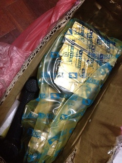
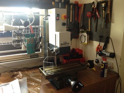
It was in July this year that I installed the scale on X axis and that was many months after I purchased the sets of scales.  I've been thinking about how to mount the scale on Z axis without drilling and tapping on any part of the mill.  This is mainly due to my lack of confident in accomplishing what many think as an easy task.

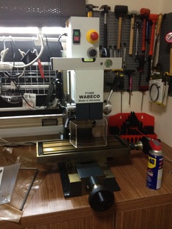
I ran across a YouTube video posted by rjkflyer sometime ago and decided to roughly follow what he did to his Wabeco F1200 mill.  His video can be found here: http://youtu.be/2z_xZFiNa14.

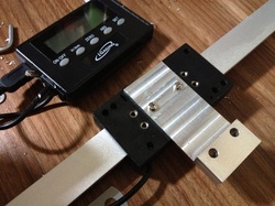
First order of the day is to find a way to mount the base of the scale.  This one is simple, I merely make a piece of 5mm thick aluminium plate with 2 clearance holes for the M4 screws to mount the plate on and a M4 hole to hold the scale.
Picture
The simplest part to make.

The challenge I faced when finding a way to attached the reading head to the spindle saddle is the availability of suitable brackets.   I contemplated buying a sheet metal bending brake to make my own but there are none available locally that is small enough for my already congested shop.  Harbor Freight in US sells an 8" version which is what I need at USD199.  But the shipping cost too much as the bending brake is rather heavy.   In the end, I settle on fabricating my own from a piece of aluminium. 
Picture
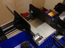
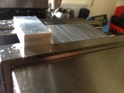
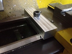
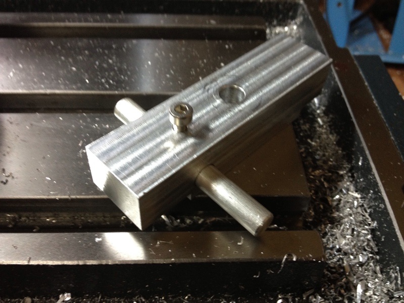
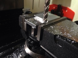
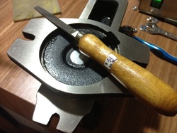
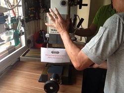
The closest aluminium plate I can find in my box is this 13mm piece.  It is too small to clamp on the bandsaw to cut it to near required size.  A long piece of square stock and the machinist jack help were employed to hold it properly during sawing.

Picture
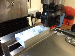
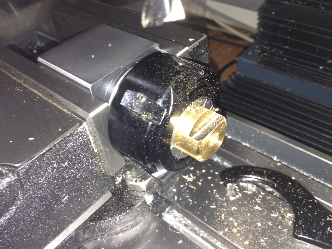
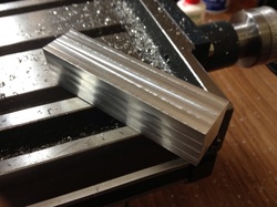
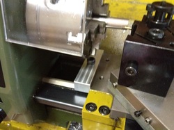
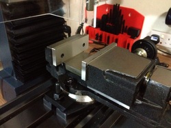
Facing the plate to required thickness of 10mm.  I've been looking for opportunity to use the facemill.  Since I've quite some meat to remove after clean up the first side, I put all all the 4 inserts to see if it works for me in this configuration.

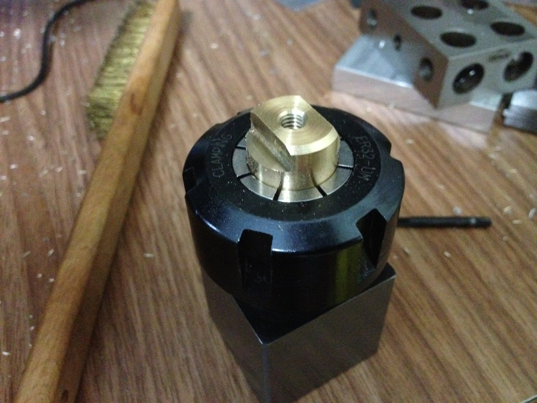
Sad to say it didn't.  The surface finish sucks!  I tried different speed, feed, and used WD40 as lubrication.  Nothing works.  1 piece of insert came off at a time and rather sad to say that I'm back to 1 insert on it.

The DOC tried were 0.1mm, 0.2mm, and 0.25mm.  The mill has an MT2 spindle bore.  If anyone has success in using this with all 4 inserts on , let me know please.

Picture
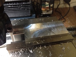
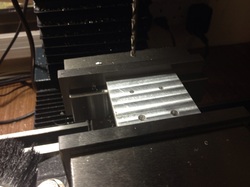
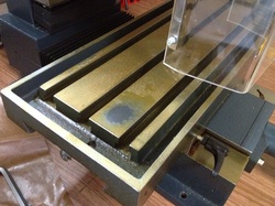
This is from using 3 inserts.  The surface is not even.

Picture
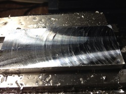
This is from using 2 inserts. Almost the same as when I was using 3 inserts.

Picture
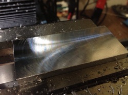
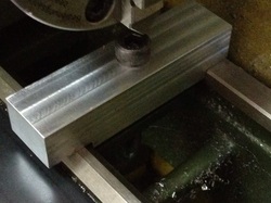
Back to 1 insert.  Better.  With WD40 and at faster speed, I achieved good finishes than what you see here.

Picture
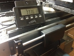
Took me a long time to get to the dimension I want.

Picture
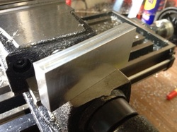
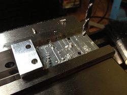
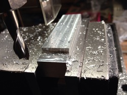
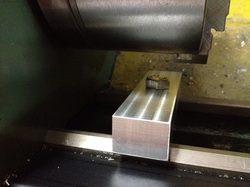
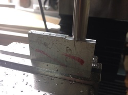
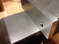
Milling off the area that the reading head will be mounted on to.  This is about 2mm thick, just before the last pass to bring it down to 1.5mm (so that I can reuse the M3 screws that came with the scales).

Picture
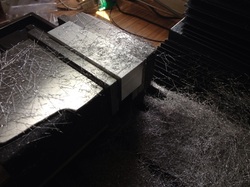
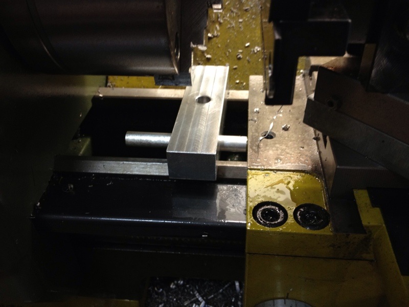
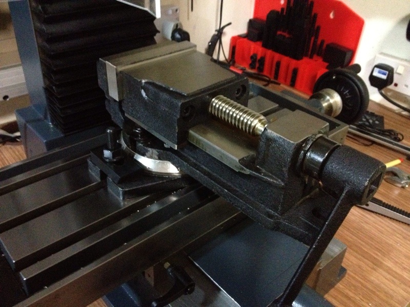
This was the scary moment.  I was left with a couple of hair before hitting the vise jaws.

Picture
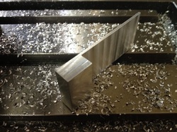
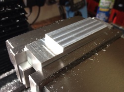
The basic shape done.  Time for mounting holes.

Picture
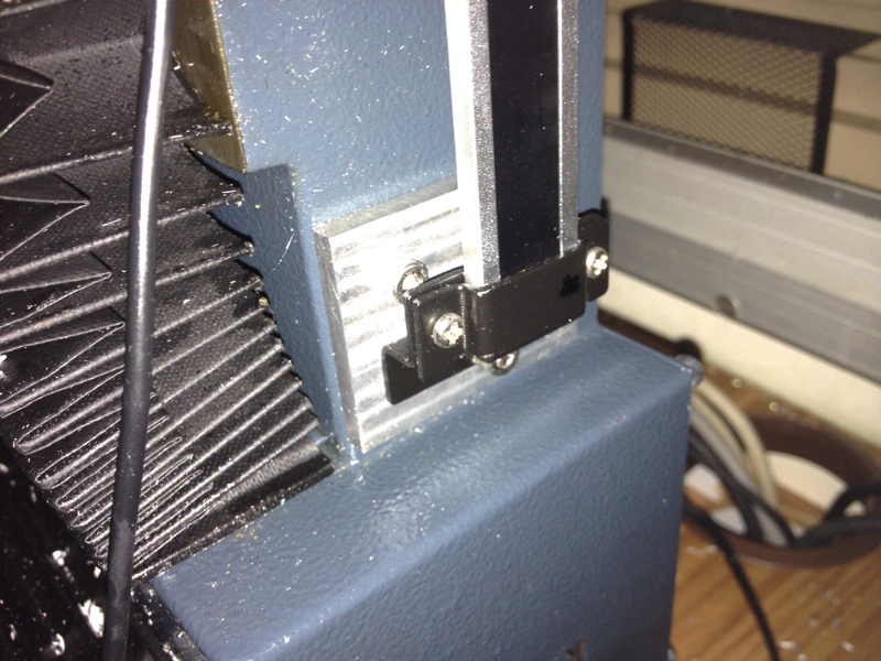
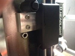
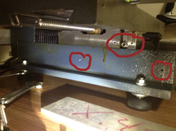
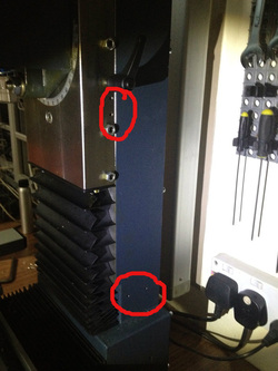
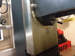
But before that, I did a dry fitting to also mark the mounting holes for the reading head (the black box with the wire sticking out of).

Picture
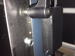
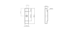
The 2 M4 holes from factory.  Thanks to emcomachineTools.co.uk, I found all the mounting holes dimensions and distance.

Picture

Picture
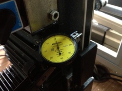
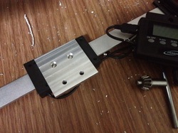
Running an indicator along the edge of the scale.  

Picture
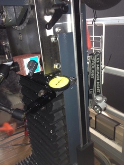
Took me a while to get it to within 0.02mm.  The edge of the reading head was then marked on the bracket.  The M4 holes on the underside of the reading head is 20mm away for its edge.

Picture
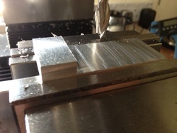
Drilling the mounting holes.
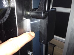
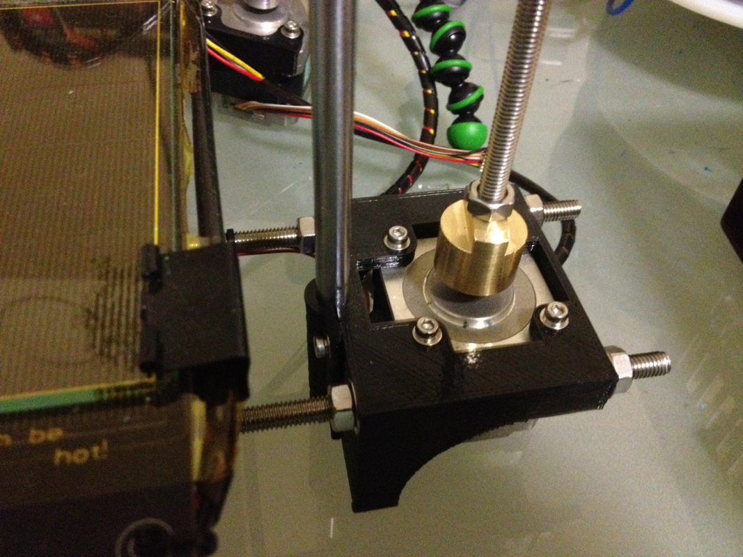
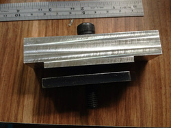
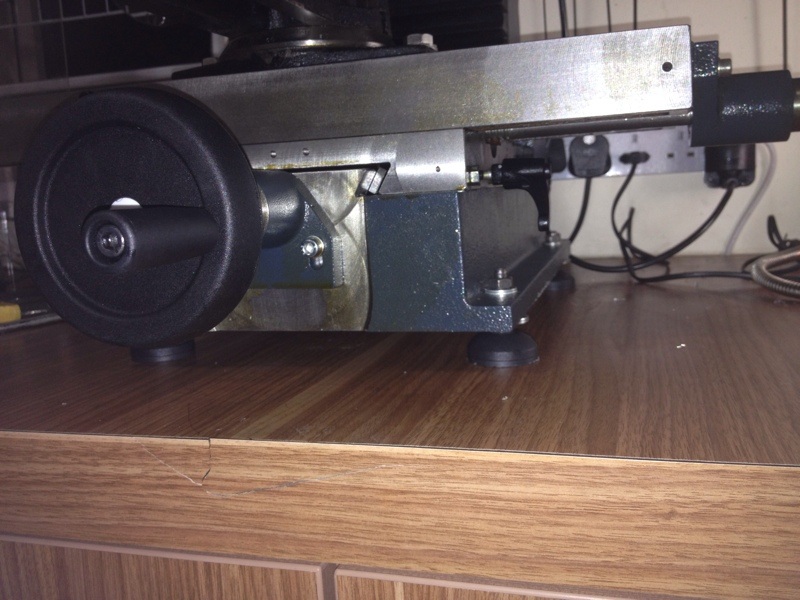
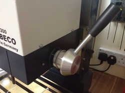
Picture
Perfect fit again!

Picture
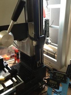
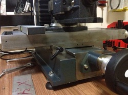
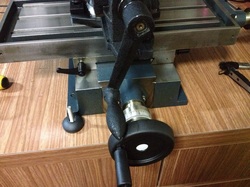
Done!  It works beautifully!  No binding along the entire length of travel.

Once I finished up with Y axis, I'll think of how I should mount the 3 DROs on the mill.

At least something being accomplished today.  Have not been productive in the shop for many months.  I'll get on with Y axis after thinking through how I should mount it.
7 Comments

The Couplers Completed

26/8/2012

0 Comments

 
Got home late yesterday night and went straight to the shop to complete the job. The aim was to make another coupler for the other stepper motor and mill the flat for adjustable wrench. The 2 couplers turned out rather different; the flats were milled too deep for one.
Picture
Picture
Picture
Picture
Picture
Hope the difference will not have any impact on the overall performance of the Z axis.

Next up, the lead screw conversion for the Sherline CNC mill. Further upgrade to the Portabee will continue after this.
0 Comments

Simple Carriage Stop

25/7/2012

0 Comments

 
As I'm to make 50 pieces of the stainless steel bushing for my dad, I'm thinking of a way to make turning to a specific length easier and more repeatable.  The carriage stop has been on my To-Do list for a long time.  But I just couldn't find a plan online that can be used on my Proxxon PD400.  The Fixed Steady I've gave me an idea though - a simple piece that clamps onto the ways of the lathe to act as a stop.
Picture
I measured the distance between the ways and the dimensions at the base of the Fixed Steady to come out with a simple diagram.

Picture
A pieces of square aluminium bar stock was used.  All faces were cleaned up and milled square.

Picture
All squared up and ready.

Picture
Milling a section 3.5mm deep.

Picture
The other end that will sit on the prism shaped way.

Picture
The assembly.  As mentioned above, the clamping plate is from the Fixed Steady.

Picture
Placed on the way to see if it holds out.

Picture
Then I realised one thing; most of the job will be done close to the chuck.  

Picture
It is, in actual fact.  I'm not able to tighten the cap screw with the allen key in this position. 

Picture
Switching to a hex head solved the problem.  Tightening is also easier with a wrench.

I carried on working on the stainless steel bushing with the stop in place.  It works rather well till a long string of swarf went in between the stop and the carriage.  This got me thinking of those pics of carriage stop I saw online.  The rod that is used on most for adjustment may be the solution to my problem since contact area is smaller.

Back to work on the mill drilling and tapping the stop.  This is what I got:
Picture
Picture
After making 2 more pieces of the bushing, I started wondering how have I been surviving without the carriage stop...  It is a simple to make, yet effective.  It makes working on the lathe so much simpler.  If I'm able to make one that will trigger the autofeed to stop, it will be even better.  The plan posted on Tools And Mods by Ralph Patterson looks simple to implement.  The plan is available for download here.  I'll study the plan to see if its simple enough for newbies like me.

Time to stop.  Now feeling that good.  The swell on my cheek doesn't seem to go away.  The stitched wound on my gum feels sore.  Guess I should wash up, make something to eat, take the many pills given to me, and go to bed.  I've a meeting to attend at 11am tomorrow.  Fixed that up last Friday.  Will continue my medical leave after tomorrow.
0 Comments

Installing iGaging Scales to the Wabeco F1200 - X Axis

13/7/2012

2 Comments

 
The iGaging Scales were purchased many months ago from Amazon.com.  Five were bought, of which 3 are supposed to be for the Sherline 5410 and 2 for the Proxxon PD400.  I never get to install them due to lack of courage in drilling and tapping holes on the machines.  The scales were just collecting dust on the shelves...

Some recent discussions on the Metalworkingfun.com stirred up the desire to have DRO on my machines again.  I was going through one of the recommended online seller, DROPros, and am interested in their Electronica Magnetic Scales.  The scales, with the DRO, for 3 axis mill are priced from USD980 excluding shipping of USD140.  That has not included GST charged for purchases above SGD400 when the items reached SG shore.  Still concerned about not having the ability to drill and tap mounting holes on the machines, I decided to use the iGaging scales with remote DRO on each axis to test things out.

The Wabeco F1200 is a good candidate for this installation as (1) it is going to be the mill that I'll be using more often, (2) it came with M4 mounting holes which I can adapt for the installation with careful planning, and (3) there is a Youtube video by rjkflyer (you can watch it here) that shows his installation of digital scales on his F1200 using the existing holes.
Picture
The X axis mounting holes can be seen clearly from this pic.  This axis should be the easiest and I'll start off with it to boost my confident.

Picture
The Y axis mounting holes.  I'm likely to fabricate a square bar of about 300mm long for the holes on the machine base.  A bracket of sort will have to be made for the 2 holes on the saddle.

I observed from moving the table forward that the saddle mounting holes moved passed the front mounting hole on the base (the hole on the right of the pic).  This means that I'll have to allow for the bar to protrude out to the front of the mill to cater for the reading head to be in the front position.

Picture
The Z axis hole locations.  2 provided at the base and 2 on the saddle.  Need to think of how the bracket should look like.

Not many pics were taken during the process of mounting the scale for the X-axis.  I spent most of the time measuring the distance between the reading head and the machine surface, the hole locations etc.  A simple bracket made from aluminium was fabricated to mount the reading head to the saddle.  The Wabeco mill is a joy to use.  I've never been able to thin down a piece of thicker stock to the required thickness in such short time.  The aluminium plate was rough cut on the bandsaw to about 50mm x 50mm and thin down to 49mm thick.  2 x 4mm holes were drilled for the hole on the saddle and 2 x 3mm for attaching the plate to the reading head.  The counterbores for the 3mm holes are a little larger than necessary as I do not have a 5.5mm or even a 6mm endmill to use.  So a 7mm was used instead. 
Picture
I started off by trimming off the rough sawn ends.  The Wabeco mill is a joy to use.  The process was a quick one.

Picture
The 2 surfaces were faced next with a 10mm endmill.  I have yet to receive the ER16 collet chuck with MT2 shank.  So tooling at the moment is limited...

Again, the process was a quick one.  I was simply gliding the cutter across the face of the workpiece... 

Picture
Mounting holes drilled; 2 x 3mm and 2 x 4mm clearance holes.

Picture
Fastening the reading head to the bracket.  The counterbores are oversize.

Picture
Installed on the mill.  The scale in use is a little short of the mounting holes but the travel of the X axis is within the travel of the scale.  Further, I realized that I do not have to cut up the longer piece I'm reserving for the Proxxon lathe as it works fine without this end shown in the pic screwed down.

I ran the axis from end to end to make sure that I do not run off the scale with the movement of the table.  Also, I get back to zero every time I return the scale to the other end of the axis - a bonus for such low price scale.

Before starting work on the scale, I installed the feet I bought.  This activity is a rather strenuous one given the weight of the mill and me working alone.  Tilting the mill and trying to free one hand to fit in the bolt took me quite a while.  I later decided to slide the mill such that the mounting hole is off the bench for easy installation.  I was so worried that the mill may fall off the bench when fixing up the feet for the holes at the back where most of the weight are behind.   Sliding the mill around was much easier but that caused the Formica at the end of the bench to crack (see pic below).
Picture
I'll be continuing with the installation of the other 2 axes when I have decided on how best to mount the scales.  Unlikely to be tonight - I'm too tired.
2 Comments

Electric Shock!

11/7/2012

0 Comments

 
I've been getting the tingling feel whenever I touch the metal surfaces of the Wabeco mill. This reminded me of the same issue I had with the Sherline 2010 mill which earth pin wasn't contacting the clip in the cheapo adapter I was using. Mike of SgTooling had me check if the earth pin has proper contact with the adapter and to change out to a better travel adapter. The more expensive adapter (read better quality) from Homefix solved the problem.

The Wabeco mill came fitted a 2-pin Europlug which has earth via 2 contacts on its top and bottom, just like what Proxxin fitted theirs with.
Picture
Sorry for the blurry pic. Using one hand to hold the plug while the other hand on the iPhone taking the pic.
I didn't have this problem with the Proxxon as I bought a suitable adapter from Mike the day I went over to his shop to inspect the lathe prior to its delivery.

I opened up the adapter Mike sold me and saw the contact for earthing:
Picture
From the pic, you can see the copper contact on the top centre. This would provide the needed connection to the earth plate on the Europlug.
Picture
This is how the Europlug looks like before applying the adapter.

Picture
With the adapter installed.  Pic taken from the plug on the Proxxon lathe.

Looks like another trip down to Mike's shop is needed... The reward of going there - my favorite Curry Chicken Noodle!  Mikey, here I come... will you help me queue up for the Curry Chicken Noodle while I make my way down during lunch?
0 Comments

Vertex Vise

9/7/2012

0 Comments

 
I just couldn't resist the temptation to act on my impulsive buying behaviour.  I was supposed to pop by Nanyang to purchase the feet for the mill and asked about milling vise with swivel base.  Jimmy, an old friend in the shop, brought me over to their other shop selling machines and tools within the same building.  15 mins later, I walked out with the vise...
Picture
The vise mounted on the mill table after cleaning up.
Last Friday while I was at Nanyang to buy the clamping kit, the big boss, CC, recommended a Matchling Hydraulic Vise which cost almost SGD600 with GST.  It looks good in the catalog and can opens up to 170mm, which CC commented that it makes full use of the table width of 180mm.  The problem I suspect is its overall length, indicated as 440mm, and it is the smallest of that model.  I was going "just buy and make it work" but caught myself.  Today, I didn't...
Picture
When I got home at almost 10pm, I rushed to my shop to rip off the box and the bag to unearth the rather heavy piece of steel.  It was sticky and messy with all the dried grease over it.

Some elbow grease was used and after almost half an hour, I've a shiny piece standing in front of me.

From the experience removing the dried grease on the Wabeco mill, I found using WD40 with an old toothbrush work better than WD40 with a piece of rag.  It still took me some time to reach within gaps a tight spots to clean out the unwanted stuff.

Picture
Nice and shiny... The protruding cap screw will be moved in from the back of the moveable block.

Picture
I didn't notice that the edges of the bottom surface were rather sharp till I see a light scratch on the table of the mill.  A smooth file was used to gently removed all sharp edges.

Picture
Maximum opening of the jaws is 60mm.

Picture
The handle is a little too long.  Fortunately, it is removeable. An adjustable wrench was used instead to open and close the jaw.

The feet in front of the mill.  This is one of the 4 I bought to install on the mill.  But I was advised against using this.

The next to purchase is the ER16 collet chuck with MT2 shank and M10 drawbar threads.  Chan Man Lee and Nanyang only have straight shank available.  Looks like CTC Tools will be my answer again.  Further, it is cheaper to get from CTC at USD15, except the longer waiting time.  But I'm left with no choice.

The DRO with glass scales are on the list of things to buy for the mill.  I'll run through the installation process in my head to see if I am up to installing the scales on the mill.

That's all for now.  Hopefully more to come soon.

Blessed night!
0 Comments

The Wabeco Mill Has Arrived!!!

8/7/2012

8 Comments

 
Picture
It had been an exciting day.  I was printing the Z endstop holder clamp to replace the one broken when the delivery man knocked on the door.  He wanted me to go down to his truck with him to inspect the goods before uncrating.  With the crate, the pallet weighs 111 kg.  So I think they were trying to remove some weight before moving the machine up to my unit which is on the 13th floor.

Picture
I was greeted with this and wondered what is there to inspect.  Maybe to see if any nails fell off during shipment?  I believe they want me to be present during the process of uncrating.

Picture
And so the process started...

Picture
Removing the top revealed the mill sealed in a foil like bag.

Picture
The 2 delivery guy working to remove the side panels of the crate while the driver giving his comments throughout the process...

Picture
The retired Commando (I was told) making a mistake by cutting the sealed bag.  The mill, with the sealed bag, was bolted to the base of the crate.  No big deal actually but comments from the driver continued... interest guy, the driver...

Picture
The gem within...

Picture
With the sides all taken off, it was time to carry the machine down to the trolley.

Picture
Mill on the move.

Picture
Right through the front door.  Welcome welcome!

Picture
This was the tough part.  With the base of the crate gone, I only allow them to carry the mill from its base.  Due to its weight, they were trying to lift it up using the table, spindle, and even the Y axis handwheel.  This made the task harder for them due also to the confined space in the shop.

Picture
But they still made it though I hawked over them to make sure they don't lift the mill on those seemingly convenient parts.

Picture
Shift the mill into position.

Picture
The table comes 3 slots of 12mm.  It is rather big, compared with my sherlines'.  A little WD40 revealed what seems to be ground surface beneath the dried grease.

Picture
The graduation marking showing the angle of the spindle for angled cuts.

Picture
The drill press type lever (what's the actual name?).  The Z axis can be moved using this (55mm stroke) or the fine feed handwheel.

Picture
The controls.  I like the big E-stop button.  Speed of the spindle can be controlled via the potientiometer with graduations from 0 - 100, corresponding to 0 - 3000 rpm.

The fine feed handwheel can be seen at the back, next to the 2-pin plug.

The good folks at Metalworkingfun suggested that I should disassemble the mill to clean out the dried grease before use.  But the axes moved so smoothly and there is a test report enclosed with the manual of the adjustments and test cuts done on this mill with the measurements of accuracy shown.  That really set me thinking if I should do that.  I had the experience of stripping and assembling the Sherlines and Proxxon before use but I don't have the confident of putting this mill back to the state after the test and adjustments were done at Wabeco factory.  Maybe I will start off by cleaning off those visible to the eyes and work from there.

I made a trip down to SG Tooling to buy another Mitutoyo Digital Vernier as the one I have has crack in the plastic case and is falling apart.  Mike was feeling generous and gave me some MT2 collets, 2 saw arbors with MT2 shank, and an MT2 flycutter.  This solved my headache of not being able to try out the mill before I order the tools and accessories I need.

I ended up also buying a 1kg roll of red filament, remembering the comments I received from a friend of mine that my blog posts on 3D printing is either in black or blue...  Now I've red... haha...

That's all for now.  My Minister of Home Affairs is hurrying me to prepare to leave our flat.  So, till next time...
8 Comments

    Enter your email address:

    Delivered by FeedBurner

    Categories

    All
    3d Printer
    Er32 Collet Chuck Proxxon
    Misc
    Misc Projects
    Projects
    Proxxon Pd400
    Sherline / A2Z Monster Mill
    Things I Bought
    Wabeco Mill

    Archives

    June 2018
    January 2017
    December 2016
    August 2015
    July 2015
    June 2014
    May 2014
    December 2013
    November 2013
    October 2013
    June 2013
    March 2013
    February 2013
    November 2012
    October 2012
    September 2012
    August 2012
    July 2012
    June 2012
    May 2012

    RSS Feed

Powered by Create your own unique website with customizable templates.